Article Content
Introduction to the ZW-10 Current Transformer
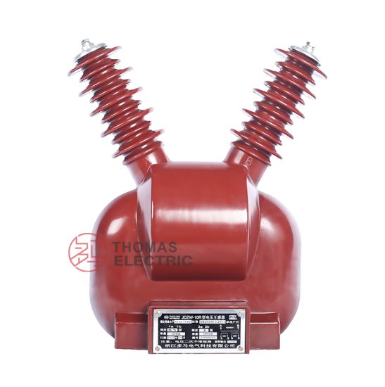
The ZW-10 is a 11kV class cast-resin insulated current transformer (CT) engineered for high-reliability metering and protection applications in medium-voltage (MV) power substations. Unlike legacy oil-immersed or gas-insulated alternatives, the ZW-10 leverages advanced epoxy resin encapsulation technology to deliver superior dielectric performance, environmental resilience, and maintenance-free operation over its service life.
Cast-Resin Insulation Technology Principles
Cast-resin insulation systems utilize thermosetting epoxy resins filled with silica or alumina micro-fillers, vacuum-cast under controlled temperature and pressure conditions around the primary conductor and secondary windings. This process eliminates air voids and moisture ingress pathways, resulting in a monolithic, hermetically sealed structure with high mechanical strength and excellent tracking resistance. The resin matrix provides uniform electric field distribution, minimizes partial discharge (PD) inception voltage, and exhibits exceptional thermal stability up to 130°C (Class B insulation per IEC 60085).
Key Advantages Over Oil-Immersed Designs
- Fire Safety: Non-flammable construction eliminates fire hazards associated with mineral oil, critical for indoor switchgear and urban substations.
- Environmental Robustness: Immune to oil leakage, oxidation, and moisture absorption; suitable for high-humidity, coastal, or polluted environments (IEC 60815 pollution severity classes).
- Maintenance Reduction: No need for periodic oil sampling, degassing, or tank integrity checks—reducing lifecycle operational expenditure (OPEX).
- Compact Footprint: Higher dielectric strength of epoxy resin allows reduced creepage and clearance distances compared to oil-paper systems, enabling space-efficient designs.
ZW-10 Specific Innovations
The ZW-10 incorporates a toroidal core fabricated from grain-oriented electrical steel (GOES) with low hysteresis loss and high permeability at nominal flux densities (typically ≤1.5 T). Secondary windings are precision-wound with enameled copper wire and embedded within the resin matrix using multi-stage vacuum impregnation to ensure complete void elimination. A shielded electrostatic screen between primary and secondary windings enhances capacitive coupling control and reduces high-frequency interference during fault transients.
Technical Specifications and Design Parameters
The ZW-10 is rated for 11kV system voltage (Um = 12kV) and designed in accordance with IEC 61869-2 and GB/T 20840.2. Its performance envelope is defined by stringent electrical, thermal, and mechanical parameters essential for reliable substation operation.
Rated Voltage, Current, and Frequency
| Parameter | Value | Standard Reference |
|---|---|---|
| System Voltage (Urms) | 11 kV | IEC 60038 |
| Highest System Voltage (Um) | 12 kV | IEC 61869-2 |
| Rated Primary Current (Ip) | 50–3000 A (standard ratios) | IEC 61869-2 Table 101 |
| Rated Secondary Current (Is) | 1 A or 5 A | IEC 61869-2 |
| Rated Frequency | 50 Hz or 60 Hz | IEC 60038 |
Insulation Levels
The ZW-10 meets standard insulation coordination requirements for 12kV class equipment:
- Power Frequency Withstand Voltage: 28 kV rms for 1 minute (phase-to-earth and phase-to-phase)
- Lightning Impulse Withstand Voltage (BIL): 75 kV peak (1.2/50 µs waveform)
- Partial Discharge Inception Level: ≤10 pC at 1.2 × Urms under factory test conditions
Accuracy Classes
Dual-winding configurations support simultaneous metering and protection functions:
- Metering Winding: Accuracy class 0.2 or 0.5 per IEC 61869-2, compliant with revenue metering requirements (e.g., EN 50163, IEEE C57.13)
- Protection Winding: Class 5P10 or 5P20, ensuring ≤5% composite error at 10× or 20× rated current with specified burden
Thermal and Dynamic Performance
The ZW-10 is rated for continuous thermal current (Ith) equal to its primary rating and short-time thermal withstand current (Ith) of 20–40 kA for 1–3 seconds, depending on ratio. Dynamic withstand current (Idyn) typically exceeds 2.5 × Ith, satisfying IEC 62271-1 mechanical stress criteria during three-phase or single-phase faults.
IEC 61869 Compliance and Standards
Compliance with IEC 61869-2 (“Instrument transformers – Part 2: Additional requirements for current transformers”) forms the regulatory backbone of the ZW-10’s design validation.
IEC 61869-2 Specific Requirements
Key mandates include:
- Definition of rated insulation level based on Um
- Accuracy limit factor (ALF) verification for protection windings
- Burden standardization (e.g., 2.5 VA, 5 VA, 10 VA, 15 VA, 30 VA)
- Temperature rise limits (≤60 K for resin above ambient at rated current)
- Marking requirements including ratio, accuracy class, burden, and polarity
Testing and Verification Procedures
All ZW-10 units undergo type, routine, and special tests as defined in Clause 7 of IEC 61869-2. Type tests (performed once per design) include temperature rise, short-circuit withstand, and impulse tests. Routine tests (100% production) encompass winding resistance, transformation ratio, polarity, and power frequency withstand.
Comparison with GB/T 20840 Standards
GB/T 20840.2 is the Chinese national adoption of IEC 61869-2, with near-identical technical content. Minor differences exist in marking conventions and optional test frequencies, but functional equivalence ensures global interoperability. Dual certification enables deployment in both domestic Chinese grids and international projects requiring IEC alignment.
International Certification Requirements
Beyond IEC and GB standards, the ZW-10 may be certified by third-party bodies such as KEMA (now DNV), CESI, or UL for specific markets. Certifications validate compliance with regional grid codes (e.g., ENTSO-E, NERC) and facilitate procurement in regulated utility environments.
Installation Guidelines and Best Practices
Proper installation is critical to preserving the ZW-10’s dielectric integrity and metrological performance.
Site Preparation and Environmental Requirements
Install in clean, dry environments with ambient temperature between –25°C and +40°C. Relative humidity should not exceed 95% non-condensing. Avoid locations with excessive vibration (>0.5 g), corrosive gases (e.g., SO₂, H₂S > 10 mg/m³), or conductive dust.
Mounting Procedures
The ZW-10 features M12 or M16 threaded inserts for secure bolting to switchgear busbars or support brackets. Torque values must comply with manufacturer specifications (typically 25–40 N·m) to prevent mechanical stress on the resin housing. For outdoor installations, use IP54-rated enclosures or weather shields to protect terminal boxes.
Electrical Connections and Grounding
- Primary conductor must be centered through the aperture to minimize asymmetry-induced errors.
- Secondary terminals must be connected with stranded copper cables (min. 2.5 mm² cross-section) and secured with anti-loosening hardware.
- Secondary circuits must be grounded at a single point (typically at the relay panel) to avoid circulating ground currents.
- Unused secondary windings must be short-circuited and grounded to prevent dangerous overvoltages.
Safety Precautions During Installation
De-energize all adjacent circuits before handling. Use insulated tools and PPE rated for 11kV. Never open-circuit a live CT secondary—this can induce lethal voltages (>1 kV) due to core saturation.
Operation and Performance Characteristics
Load Behavior and Burden Considerations
The total burden (Zb) is the vector sum of relay impedance, lead resistance, and contact resistance. Exceeding rated burden degrades accuracy and increases phase error. For 5 A secondaries, lead resistance should be minimized (<0.1 Ω per conductor for 0.2-class metering).
Transient Response Characteristics
During high-magnitude faults, the core may saturate if the DC offset exceeds the remanence limit. The 5P20 rating ensures linear response up to 20× rated current with ≤5% error, provided burden does not exceed 30 VA. Core design includes air gaps or high-saturation steel to mitigate remanence effects.
Temperature Rise and Thermal Management
At rated current, temperature rise is limited to 60 K above ambient. Resin’s thermal conductivity (~0.8 W/m·K) facilitates heat dissipation to ambient air. Continuous overload beyond 120% of Ip risks accelerated aging and PD activity.
Partial Discharge Performance
Factory-tested PD levels are maintained below 10 pC at 1.2 × Urms. Field PD measurements using IEC 60270 methods can detect insulation degradation. Sustained PD >50 pC indicates potential void formation or moisture ingress requiring investigation.
Testing Procedures and Quality Assurance
Factory Acceptance Testing (FAT)
FAT includes:
- Ratio and polarity verification via bridge or digital ratio tester
- Winding resistance measurement (corrected to 75°C)
- Power frequency withstand (28 kV, 1 min)
- Partial discharge measurement (IEC 60270)
- Accuracy verification at 5%, 20%, 100%, and 120% of rated current
Site Commissioning Tests
Post-installation tests include:
- Insulation resistance (≥1000 MΩ at 2500 V DC)
- Secondary circuit continuity and polarity check
- Burden verification using injected current
- Relay pickup testing with simulated fault currents
Routine and Type Tests per IEC 61869-2
Type tests (design validation): temperature rise, short-circuit, impulse, and dynamic tests. Routine tests (production): ratio, polarity, insulation, and accuracy at 100% current.
Diagnostic Testing Methods
Advanced diagnostics include frequency response analysis (FRA) for winding deformation and dielectric frequency response (DFR) for moisture assessment—though less common for cast-resin CTs due to their solid insulation.
Maintenance and Troubleshooting
Preventive Maintenance Schedules
Cast-resin CTs require minimal maintenance. Recommended intervals:
- Annual: Visual inspection for cracks, discoloration, or tracking
- Triennial: Insulation resistance and secondary circuit integrity test
- After major fault: Accuracy re-verification and PD check
Common Fault Diagnosis
- Inaccurate metering: Check burden, secondary connections, or core saturation.
- Overheating: Verify current magnitude and ventilation; inspect for loose connections.
- Cracking or charring: Indicates thermal runaway or external arc flash—replace immediately.
Insulation Resistance Testing
Use a 2500 V megohmmeter between primary-ground and secondary-ground. Values below 100 MΩ warrant further investigation. Note: Resin CTs exhibit lower IR than oil-filled units due to surface leakage—clean terminals before testing.
When to Replace vs Repair
Cast-resin CTs are not field-repairable. Replace if:
- Visible structural damage
- Insulation resistance <50 MΩ after cleaning
- Accuracy deviation >2× class limit
- Partial discharge >100 pC at operating voltage
Application Scenarios and System Integration
Substation Metering Applications
The 0.2-class winding interfaces with kWh meters, AMI systems, and tariff analyzers. Low phase error (<10 minutes) ensures compliance with billing regulations (e.g., EU Measuring Instruments Directive).
Protection Relay Coordination
5P20 windings feed overcurrent, differential, and distance relays. Proper ALF selection ensures relay operates within its time-current curve during faults while avoiding nuisance tripping during motor starts or transformer inrush.
Integration with SCADA Systems
Secondary outputs connect to RTUs or IEDs via shielded twisted-pair cables. Modern digital substations may use merging units (per IEC 61850-9-2) with analog-to-digital conversion at the CT location.
Case Studies and Field Experience
In a 110/11kV urban substation in Guangdong, ZW-10 units have operated continuously since 2018 with zero failures. Accuracy drift measured annually remains within ±0.1%—demonstrating long-term stability of cast-resin technology under tropical conditions.
FAQ1: Can the ZW-10 be used in outdoor switchyards without an enclosure?
While the cast-resin body is UV-resistant and hydrophobic, prolonged exposure to direct sunlight and rain may degrade terminal box seals. Outdoor installations should use IP54-rated protective housings or conformal-coated terminal blocks to ensure long-term reliability.
FAQ2: What is the maximum allowable secondary burden for a 5P20 winding?
The rated burden (e.g., 30 VA) defines the maximum load at which the 5% composite error limit applies at 20× rated current. Exceeding this burden increases error nonlinearly. Always verify burden using actual relay impedance plus lead losses.
FAQ3: How does temperature affect ZW-10 accuracy?
Temperature coefficients for ratio and phase error are typically <±0.05%/°C within –25°C to +40°C. Extreme cold may slightly increase core reluctance, while high ambient temperatures reduce copper conductivity—both effects are compensated in precision winding design.
FAQ4: Is the ZW-10 suitable for harmonic-rich environments (e.g., near VFDs)?
Yes, provided harmonic currents do not cause core saturation. The GOES core has sufficient margin for typical 5th and 7th harmonics. However, for significant 3rd harmonic content (zero-sequence), consider using a dedicated zero-sequence CT.
FAQ5: What is the expected service life of the ZW-10?
Under normal operating conditions (≤1.2× rated current, ≤40°C ambient), the design life exceeds 30 years. Accelerated aging occurs only under sustained overload, high PD activity, or mechanical shock.
FAQ6: Can multiple ZW-10 units be installed in close proximity?
Yes, but maintain minimum spacing of 100 mm between units to avoid magnetic coupling between cores, which could induce ratio errors. Align primary conductors coaxially to minimize stray fields.