Product Overview
Functional Definition
The JDJ series oil-immersed voltage transformers (including JDJ-3, JDJ-6, JDJ-10, and JDJ-12 models) are precision electromagnetic instruments designed for accurate voltage measurement, energy metering, and relay protection applications in medium-voltage AC power systems up to 12 kV class. These transformers utilize electromagnetic induction principles to provide galvanically isolated secondary voltage signals proportional to primary voltage, enabling safe measurement and protection at standardized secondary voltage levels.
Key Ratings
| Item | Specification (per order / nameplate) |
|---|---|
| System voltage class | JDJ-3: 3 kV; JDJ-6: 6 kV; JDJ-10: 10 kV; JDJ-12: 12 kV class (indoor applications) |
| Rated frequency | 50 Hz (60 Hz available upon request) |
| Rated primary voltage | Per voltage class (line-to-ground): 3/√3 kV, 6/√3 kV, 10/√3 kV, 12/√3 kV |
| Rated secondary voltage | JDJ-3/6/10: 100 V; JDJ-12: 110 V (per voltage ratio / nameplate) |
| Accuracy classes | Metering and/or protection cores as specified (e.g., 0.2 / 0.5, 3P) |
| Rated burden | Per core/winding as specified (VA) |
| Burden power factor | cosφ = 0.8 (lagging) unless otherwise specified by the project standard |
| Insulation type | Oil-immersed insulation system with laminated core construction |
| Applicable standards | IEC 61869-1 / IEC 61869-3; GB/T 20840.1 / 20840.3; GB 1207-2006; DL/T 866 |
| Service conditions | Indoor installation; altitude ≤1000 m; -5°C to +40°C ambient |
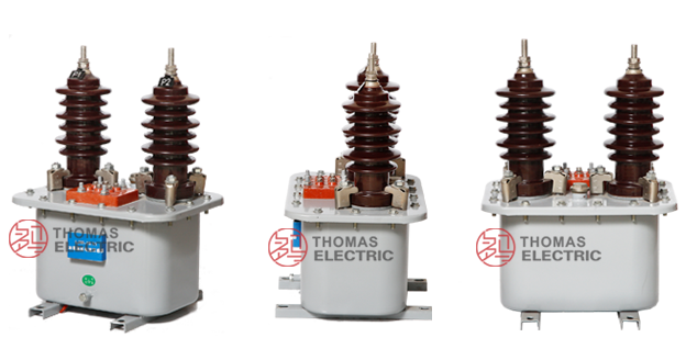
Product Shows
 Thomas Electric")
 Thomas Electric")
Working Principle
Operating on Faraday’s law of electromagnetic induction, the voltage transformer features a laminated iron core with primary and secondary windings concentrically wound on the same core. The alternating voltage applied to the primary winding generates magnetic flux in the core, which induces proportional voltage in the secondary winding according to the turns ratio. The oil-immersed construction provides superior insulation and heat dissipation, ensuring stable operation under continuous service conditions.
System Application Position
- Medium Voltage Distribution: 3-10kV switchgear and distribution panels
- Energy Metering: Revenue-grade electricity measurement systems
- Protection Circuits: Overvoltage, undervoltage, and distance protection schemes
- Voltage Monitoring: System voltage indication and recording equipment
- SCADA Integration: Supervisory control and data acquisition systems
Structural Overview
Oil-immersed insulation construction with laminated silicon steel core and concentrically wound primary and secondary windings. The transformer assembly is mounted on the top cover and immersed in insulating oil within a sealed tank, with oil level maintained 10-15 mm below the cover. High-voltage and low-voltage connections are brought out through porcelain bushings, providing reliable insulation clearance and ease of installation. The sealed tank design with oil filling port facilitates maintenance and inspection operations.
Model Designation
 Thomas Electric")
Model Code Explanation
- J — Voltage transformer (VT)
- D — Single-phase
- J — Oil-immersed insulation
- 3 / 6 / 10 / 12 — Voltage class (kV)
Variant Comparison
JDJ-3, JDJ-6, JDJ-10, and JDJ-12 share the same construction principle and differ primarily in voltage rating and insulation coordination. In some specifications, “JDJ-12” is used to denote the 10–12 kV class naming convention (highest system voltage Um = 12 kV). Final selection shall follow the project voltage class and the nameplate.
Service Conditions
The JDJ series voltage transformers are designed for indoor operation under normal service conditions in medium-voltage power systems.
- Installation environment: Indoor installation only
- Altitude: Not exceeding 1000 m above sea level (higher altitude shall be specified for engineering confirmation)
- Ambient temperature: −5 °C to +40 °C
- Relative humidity: ≤ 85% at +20 °C reference
- Seismic withstand: 0.4g direct vibration test (equivalent to magnitude 9 seismic intensity)
- Environmental conditions: Free from corrosive gases or vapors; free from explosive or flammable media; no severe vibration, mechanical shock, or impact
Construction
Construction Design
- Structure: Post-type for indoor switchgear mounting
- Insulation: Oil-immersed insulation system
- Core: Laminated silicon steel core design
- Windings: Concentrically wound primary and secondary on common core
- Tank: Sealed oil tank with porcelain bushings
- Oil level: Maintained 10-15 mm below tank cover
The oil-immersed construction provides excellent insulation properties, effective heat dissipation, and resistance to moisture and contamination for long-term indoor service.
Windings & Terminal Marking
 Thomas Electric")
- Primary terminals: A / X (single-phase primary)
- Secondary terminals (Metering winding): a / x
- Secondary terminals (Protection winding, if equipped): ad / xd
Terminal markings follow standard VT polarity conventions. Under normal operating conditions, when primary terminal A is at positive potential relative to X, secondary terminal a is simultaneously at positive potential relative to x. Correct terminal identification shall be observed to ensure metering and protection performance.
Technical Data
This section provides selection-oriented technical data for the JDJ-3, JDJ-6, and JDJ-10 series oil-immersed voltage transformers used in 3 kV, 6 kV, and 10 kV class AC systems (50 Hz). Data shown below is intended for preliminary selection of accuracy class combinations, rated burdens, and voltage ratings.
Definitions: Accuracy class indicates metering and/or protection performance (multi-core configuration may apply). Rated output (VA) is specified per secondary winding. Voltage factor defines the permissible continuous overvoltage capability.
Notation: Technical parameters shall be confirmed based on nameplate values and factory test report for each specific order.
Data Reference
| Type | Rated Voltage Ratio (V) |
Corresponding (VA) | Limit Output (VA) |
Power Frequency Withstand (kV) |
Weight (kg) |
|||
|---|---|---|---|---|---|---|---|---|
| 0.2 | 0.5 | 1 | 3 | |||||
| JDJ-3 | 3000/100 | 20 | 30 | 50 | 120 | 240 | 24 | 46.5 |
| JDJ-6 | 6000/100 | 30 | 50 | 80 | 200 | 400 | 32 | |
| JDJ-10 | 10000/100 | 40 | 80 | 150 | 320 | 640 | 42 | |
| JDJ-12 | 11000/110 | 40 | 80 | 150 | 320 | 640 | 42 | |
Standards & Normative References
| Standard | Title | Application |
|---|---|---|
| IEC 61869-1 | Instrument Transformers – Part 1: General Requirements | General requirements |
| IEC 61869-3 | Instrument Transformers – Part 3: Additional Requirements for Voltage Transformers | VT-specific requirements |
| GB/T 20840.1 | Instrument Transformers – Part 1: General Requirements | National standard (aligned with IEC 61869 framework) |
| GB/T 20840.3 | Instrument Transformers – Part 3: Voltage Transformers | National VT requirements (aligned with IEC 61869-3) |
| GB 1207-2006 | Voltage Transformers | National VT standard where specified by the project |
| DL/T 866 | Technical Specification for Medium Voltage Instrument Transformers | Power industry technical requirements |
| IEEE C57.13 | Standard Requirements for Instrument Transformers | Optional (North America project reference) |
| IEC 60085 | Electrical Insulation – Thermal Evaluation | Optional (insulation thermal evaluation reference) |
Factory Test Compliance
- Routine tests per applicable IEC/GB requirements (including polarity/marking, ratio verification, and accuracy verification per specified class and burden)
- Dielectric tests per insulation coordination requirements and applicable standard
- Voltage factor test per specified overvoltage capability
- Visual and dimensional inspection including marking and workmanship conformity
- Type and special tests as required by the project specification
Installation & Dimensions
- Outline dimensions and mounting details are provided in the dimensional drawings.
- The transformer shall be securely mounted using the designated fixing holes on the mounting base.
- Primary and secondary connections are made via porcelain bushing terminals.
- Adequate clearance shall be maintained for insulation, heat dissipation, and maintenance access.
- Oil level shall be verified before commissioning and maintained within specified range.
Connection Diagrams
 Thomas Electric")
Outline & Installation Dimensions
 Thomas Electric")
Ordering Information
When placing an order, the required configuration shall be specified according to the local grid requirements, applicable standards, and project technical specification. The following parameters shall be clearly stated for technical confirmation and production release:
- Model designation (JDJ-3, JDJ-6, JDJ-10, or JDJ-12)
- Rated primary voltage / voltage ratio
- Rated secondary voltage (100 V or 100/√3 V)
- Application and accuracy requirements (metering and/or protection accuracy class combination)
- Rated burden (VA) for each secondary winding
- Voltage factor requirements (continuous and short-time overvoltage capability)
Selection guidance:
1: Determine system voltage class (3 kV, 6 kV, or 10 kV) and corresponding rated primary voltage.
2: Select metering and/or protection accuracy requirements (e.g., 0.2 / 0.5 for metering; 3P for protection).
3: Confirm rated burden (VA) for each secondary circuit based on connected meters/relays and wiring losses.
4: Verify voltage factor requirement against system overvoltage conditions and protection coordination.
If local utility or project requirements apply (e.g., insulation level, terminal arrangement, mounting constraints, documentation language, or required certificates), specify them at the ordering stage. Special configurations shall be confirmed by technical agreement and final data sheet prior to production.