Product Overview
The JDJ2-35 and JDJJ2-35 (also designated as JDXN2-33, JDN2-33) series voltage transformers, are single-phase outdoor oil-immersed potential transformer, this electromagnetic instruments are designed for accurate voltage measurement, energy metering, voltage monitoring, and relay protection applications in 35kV AC power systems operating at 50 Hz or 60 Hz. These transformers utilize electromagnetic induction principles to provide galvanically isolated secondary voltage signals proportional to primary voltage.
Key Ratings
| Item | Specification (per order / nameplate) |
|---|---|
| System voltage class | 35 kV class (outdoor distribution and substation applications) |
| Rated frequency | 50 Hz (60 Hz available upon request) |
| Rated primary voltage | 33000 V / 33000/√3 V |
| Rated secondary voltage | 100 V / 100/√3 V / 100/3 V |
| Accuracy classes | Metering and/or protection cores as specified (e.g., 0.2, 0.5, 1, 6P) |
| Rated burden | Per core/winding as specified (VA): 30-150 VA for metering, 100 VA for protection |
| Burden power factor | cosφ = 0.8 (lagging) unless otherwise specified by the project standard |
| Rated insulation level | 40.5/95/200 kV (Um/ACWV/LI) |
| Limiting output | 500-1000 VA depending on configuration |
| Applicable standards | GB 1208-1997; IEC 60044-2 (IEC 186) |
| Structural variants | JDJ2-35 (single/dual winding) / JDJJ2-35 (three-winding with residual winding) |
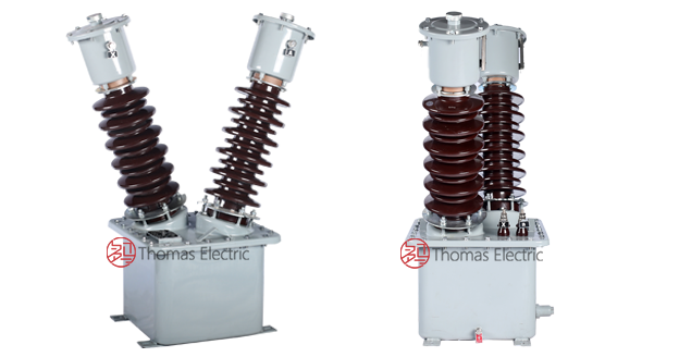
Product Shows

Working Principle
Operating on Faraday’s law of electromagnetic induction, the transformer features a three-limb laminated silicon steel core with primary winding on the center limb and secondary windings wound concentrically around the primary. The alternating magnetic flux generated by primary voltage induces proportional voltage in the secondary windings, delivering standardized output voltage through connected burden. Oil immersion provides enhanced insulation and heat dissipation.
System Application Position
- Medium Voltage Distribution: 35kV outdoor substations and distribution networks
- Energy Metering: Revenue-grade electricity measurement and billing systems
- Voltage Monitoring: Real-time voltage level supervision and recording
- Protection Circuits: Overvoltage, undervoltage, and directional protection schemes
- SCADA Integration: Supervisory control and data acquisition for utility networks
Structural Overview
Oil-immersed construction with three-limb laminated silicon steel core ensures superior insulation performance, thermal stability, and mechanical strength. The outdoor post-type mounting configuration provides robust installation in exposed environments while maintaining excellent electrical clearance and creepage distances. JDJJ2-35 incorporates a residual winding for enhanced fault protection capability in systems requiring ground fault detection.
Model Designation

Model Code Explanation
- J — Voltage transformer (PT/VT)
- D — Single-phase
- J — Oil-immersed insulation
- (J) — Ground protection
- 2 — Design code (platform/iteration)
- 35 — Voltage class (kV)
Variant Differences
JDJ2-35 is available in single-winding or dual-winding configurations for basic metering and protection applications. JDJJ2-35 incorporates a three-winding design with residual winding output (100/3 V or 100/√3 V), specifically engineered for applications requiring ground fault detection and enhanced protection coordination in outdoor distribution systems.
Service Conditions
The JDJ2-35 and JDJJ2-35 series voltage transformers are designed for outdoor operation under normal service conditions in medium-voltage power systems.
- Installation environment: Outdoor installation
- Altitude: Not exceeding 2500 m (higher altitude shall be specified for engineering confirmation)
- Ambient temperature: −25 °C to +40 °C
- Relative humidity: Not exceeding 85% at +20 °C reference
- Environmental conditions: Free from conductive dust and corrosive gases; no severe vibration, mechanical shock, or impact
Construction
Construction Design
- Structure: Post-type for outdoor substations and distribution networks
- Insulation: Oil-immersed with three-limb laminated silicon steel core
- Core: Three-limb laminated silicon steel design with center-limb winding arrangement
- Tank: Welded steel construction with grounding terminal, oil drain valve, and mounting provisions
- Conservator: Oil level gauge with square or cylindrical conservator tank
- System: Integrated primary and secondary bushing system with porcelain or composite insulators
The oil-immersed structure provides enhanced insulation properties, superior heat dissipation, and effective resistance to moisture and high-temperature environments for long-term outdoor service.
Windings & Terminal Marking

JDJ2-35 (single/dual winding):
- Primary terminals: A / X
- Secondary terminals (Winding 1): a / x
- Secondary terminals (Winding 2, if equipped): aₙ / xₙ
JDJJ2-35 (three-winding):
- Primary terminals: A / X
- Secondary terminals (Metering/Protection Winding 1): a₁ / x₁
- Secondary terminals (Metering/Protection Winding 2): a₂ / x₂
- Residual winding terminals: aₙ / xₙ (open delta configuration for ground fault detection)
Terminal markings follow standard VT polarity conventions. Under normal operating conditions, when primary terminal A is positive relative to X, secondary terminal a is positive relative to x. Correct terminal identification shall be observed to ensure metering and protection performance.
Technical Data
This section provides selection-oriented technical data for the JDJ2-35 and JDJJ2-35 series outdoor, oil-immersed voltage transformers used in 35 kV class AC systems (50 Hz). Data shown below is intended for preliminary selection of voltage ratio, accuracy class combinations, and rated burdens.
Definitions: Accuracy class combination indicates available metering/protection cores in one VT (multi-core configuration may apply). Rated output (VA) is specified per secondary core. Limiting output (VA) is the maximum continuous thermal capacity of the transformer under specified operating conditions.
Data Reference
| Model | Rated Voltage Ratio (V) |
Rated Output (VA) |
Rated Output (VA) |
Rated Output (VA) |
Rated Output (VA) |
Limiting Output (VA) |
|---|---|---|---|---|---|---|
| 0.2 | 0.5 | 1 | 6P | |||
| JDJ2-33 | 33000/100 | 50 | 100 | 150 | – | 1000 |
| JDJJ2-33 | 33000/√3 / 100/√3 / 100/3 | 50 | 100 | 150 | 100 | 2 × 500 |
| JDJJ2-33 | 33000/√3 / 100/√3 / 100/√3 / 100/3 | 30 | 60 | – | 100 | 2 × 500 |
Standards & Normative References
| Standard | Title | Application |
|---|---|---|
| GB 1208-1997 | Voltage Transformers | National VT standard (primary compliance basis) |
| IEC 60044-2 | Instrument Transformers – Part 2: Inductive Voltage Transformers | International VT requirements (IEC 186 superseded) |
| IEC 61869-3 | Instrument Transformers – Part 3: Additional Requirements for Inductive Voltage Transformers | Updated international VT standard |
| GB/T 20840.3 | Instrument Transformers – Part 3: Inductive Voltage Transformers | National standard (aligned with IEC 61869 framework) |
| DL/T 866 | Technical Specification for Oil-Immersed Voltage Transformers | Power utility technical requirements |
| GB 311.1 | Insulation Co-ordination – Part 1: Definitions, Principles and Rules | Insulation level coordination |
Factory Test Compliance
- Routine tests per applicable IEC/GB requirements (including polarity/marking, ratio verification, accuracy verification per specified class and burden)
- Dielectric tests per insulation coordination requirements: power-frequency withstand test, lightning impulse withstand test
- Temperature rise test per applicable standard to verify thermal performance
- Visual and dimensional inspection including marking, oil level, and workmanship conformity
- Type and special tests as required by the project specification
Installation & Dimensions
- Outline dimensions and mounting details are provided in the dimensional drawings.
- The transformer shall be securely mounted using the designated fixing holes on the base.
- Primary conductor connection is made via outdoor bushing terminal (porcelain or composite insulator).
- Secondary terminals are accessible through the terminal compartment on the tank side.
- Adequate clearance shall be maintained for insulation, heat dissipation, oil level monitoring, and maintenance access.
- Oil level shall be monitored via the oil level gauge on the conservator tank.
Outlines

JDJ2-35 Dimensional Drawing

JDJJ2-35 (JDXN2-33) Dimensional Drawing
Safety Notes
- Secondary circuit must never be left open when the transformer is energized, as excessive voltage may appear across the secondary terminals under certain fault conditions.
- During inspection or maintenance, the secondary circuit shall be short-circuited before disconnecting any instruments.
- One point of the secondary circuit should be reliably grounded in accordance with applicable standards.
- All installation and maintenance work shall comply with local electrical safety regulations.
- Oil level shall be monitored regularly. Do not operate with oil level below minimum marking.
- Periodic oil quality testing shall be performed per applicable maintenance standards.
Ordering Information
When placing an order, the required configuration shall be specified according to the local grid requirements, applicable standards, and project technical specification. The following parameters shall be clearly stated for technical confirmation and production release:
- Model designation (JDJ2-35 or JDJJ2-35)
- Rated voltage ratio (primary/secondary voltage)
- Rated frequency (50 Hz or 60 Hz)
- Application and accuracy requirements (metering and/or protection accuracy class combination)
- Rated burden (VA) for each secondary core/winding
- Insulation level (if different from standard 40.5/95/200 kV)
- Special requirements (residual winding configuration, terminal arrangement, documentation language, certificates)
Selection Guidance
- Determine rated primary voltage based on system nominal voltage (33 kV or 33/√3 kV).
- Select metering and/or protection accuracy requirements (e.g., 0.2 / 0.5 for metering; 6P for protection).
- Confirm rated burden (VA) for each secondary circuit based on connected meters/relays and wiring losses.
- Verify residual winding requirement for ground fault detection (JDJJ2-35 configuration).
- Confirm insulation level matches system insulation coordination requirements.
If local utility or project requirements apply (e.g., altitude correction factors, seismic requirements, special oil specifications, terminal arrangement, mounting constraints, documentation language, or required certificates), specify them at the ordering stage. Special configurations shall be confirmed by technical agreement and final data sheet prior to production.