Product Overview
Functional Definition
The JDZJ series single-phase epoxy resin voltage transformers (including JDZJ-3, JDZJ-6, and JDZJ-10 models) are precision electromagnetic instruments designed for accurate voltage measurement, energy metering, and relay protection in medium-voltage AC power systems operating at 50 Hz. Based on electromagnetic induction principles, these voltage transformers provide galvanically isolated secondary voltage signals proportional to the primary voltage, supporting reliable monitoring, metering, and protective functions in 3–10 kV distribution networks.
Key Ratings
The following table summarizes the principal electrical and mechanical ratings of the JDZJ-3, JDZJ-6, and JDZJ-10(W) single-phase epoxy resin voltage transformers. Specific values are subject to order confirmation and nameplate data.
| Item | Specification (per order / nameplate) |
|---|---|
| System voltage class | 3 kV, 6 kV, or 10 kV class (indoor distribution applications) |
| Rated frequency | 50 Hz |
| Voltage ratio | JDZJ-3: 3000/√3/100/√3/100/3 JDZJ-6: 6000/√3/100/√3/100/3 JDZJ-10: 10000/√3/100/√3/100/3 |
| Accuracy classes | 0.5 / 1 / 3 (as specified) |
| Rated output | JDZJ-3(W): 30 VA (0.5), 50 VA (1), 80 VA (3) JDZJ-6(W): 50 VA (0.5), 80 VA (1), 200 VA (3) JDZJ-10(W): 80 VA (0.5), 150 VA (1), 300 VA (3) |
| Maximum output | JDZJ-3: 200 VA / JDZJ-6: 400 VA / JDZJ-10: 500 VA |
| Insulation level (kV) | JDZJ-3: 3.5/23/40 JDZJ-6: 6.9/32/60 JDZJ-10: 12/42/75 |
| Seismic capacity | 0.4g test (equivalent to intensity IX) |
| Construction | Epoxy resin cast, single-phase, dual winding |
| Applicable standards | GB 1207 / IEC 61869-3 / IEC 61869-1 |
| Model variants | JDZJ-3(W), JDZJ-6(W), JDZJ-10(W) |
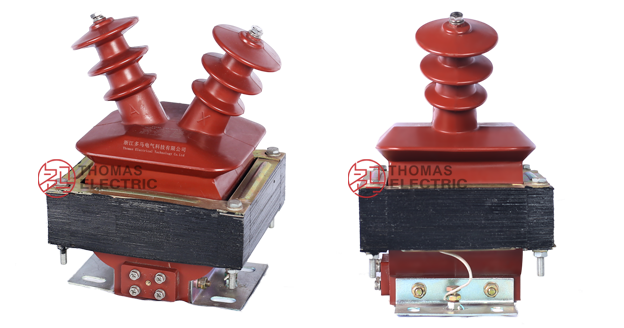
Product Shows
 Thomas Electric")
Working Principle
Operating on Faraday’s law of electromagnetic induction, the voltage transformer (VT) features a laminated ring-type magnetic core with concentrically arranged primary and secondary windings. The alternating voltage applied to the primary winding generates alternating magnetic flux in the core, inducing a proportional voltage in the secondary winding. The transformer provides galvanic isolation while delivering standardized secondary voltage outputs (typically 100 V or 100/√3 V) for metering, monitoring, and protection devices.
System Application Position
- Medium Voltage Distribution: 3-10 kV switchgear and distribution panels
- Energy Metering: Revenue-grade electricity measurement systems
- Voltage Monitoring: Real-time voltage surveillance and quality assessment
- Protection Circuits: Overvoltage, undervoltage, and directional protection schemes
- SCADA Integration: Supervisory control and data acquisition systems
Structural Overview
Epoxy resin cast construction with fully-enclosed design ensures superior insulation performance, moisture resistance, and mechanical strength. The single-phase configuration with dual secondary windings provides flexibility for simultaneous metering and protection applications. The compact vertical mounting design enables efficient space utilization in indoor switchgear environments while maintaining excellent electrical clearance and creepage distances.
Model Designation
 Thomas Electric")
Model Code Explanation
- J — Voltage transformer (VT)
- D — Single-phase configuration
- Z — Indoor support (pillar) type
- J — Epoxy resin cast insulation structure
- 3 / 6 / 10 — Voltage class (kV): 3 kV, 6 kV, or 10 kV
- (W) — Optional outdoor or pollution withstand variant (when specified)
This model designation system allows quick identification of voltage class, insulation structure, installation type, and environmental capability for engineering selection.
Variant Differences
JDZJ-3(W), JDZJ-6(W), and JDZJ-10(W) share identical construction principles but are designed for different voltage classes. The (W) suffix indicates enhanced environmental capability for specific applications. Each model is optimized for its respective voltage class with appropriately scaled insulation levels and rated outputs.
Service Conditions
The JDZJ series epoxy resin voltage transformers are intended for indoor operation under standard service conditions in medium-voltage AC power distribution systems.
- Installation environment: Indoor installation (moderate pollution environment capability)
- Altitude: Not exceeding 1000 m above sea level (higher altitude shall be specified for engineering confirmation)
- Ambient temperature: −5 °C to +40 °C
- Relative humidity: ≤ 85% at +20 °C
- Seismic capacity: 0.4g horizontal acceleration (equivalent to seismic intensity IX)
- Environmental conditions: Free from corrosive gases or vapors; free from explosive or flammable media; no severe vibration or mechanical shock
Construction
Construction Design
- Structure: Single-phase, support (post) type for indoor switchgear
- Insulation: Fully enclosed epoxy resin cast insulation
- Core: Laminated ring-type magnetic core design
- Windings: Dual secondary windings (concentric arrangement with primary)
- System: Integrated insulation system with primary and secondary isolation
The epoxy resin casting provides stable insulation properties and resistance to moisture, contamination, and aging for long-term indoor service. Primary and secondary windings are arranged concentrically on the ring-type core, with complete encapsulation in epoxy resin ensuring mechanical stability and electrical integrity.
Windings & Terminal Marking
 Thomas Electric")
- Primary terminals: A / X (high voltage side)
- Secondary terminals (Group 1): a / x
- Secondary terminals (Group 2): a / x (where dual secondaries are provided)
Terminal markings follow standard VT polarity conventions. Primary connection is made via top-mounted high-voltage terminals (A, X), while secondary outputs are accessible via bottom-mounted screw terminals. Correct terminal identification shall be observed to ensure metering and protection performance.
Connection Diagrams
 Thomas Electric")
Three-phase line connection diagram (reference)
Technical Data
This section provides selection-oriented technical data for the JDZJ series single-phase epoxy resin cast voltage transformers (JDZJ-3, JDZJ-6, and JDZJ-10(W)) used in 3–10 kV class AC systems operating at 50 Hz.
Definitions: Accuracy class indicates measurement precision per IEC 61869-3 and GB 1207. Rated output (VA) is the secondary burden capacity at specified accuracy. Insulation level is expressed as Um/Ud/Up (system voltage / power frequency withstand / lightning impulse withstand) in kV.
Customization: Voltage ratios, secondary outputs, accuracy classes, and insulation levels can be customized to meet specific system performance and environmental requirements. Contact engineering for non-standard configurations.
Data Reference
| Parameter | JDZJ-3(W) | JDZJ-6(W) | JDZJ-10(W) |
|---|---|---|---|
| Rated voltage ratio | 3000/√3/100/√3/100/3 | 6000/√3/100/√3/100/3 | 10000/√3/100/√3/100/3 |
| Rated frequency (Hz) | 50 | 50 | 50 |
| Rated output (VA) 0.5 class 1 class 3 class |
30 50 80 |
50 80 200 |
80 150 300 |
| Maximum output (VA) | 200 | 400 | 500 |
| Insulation level (kV) Um / Ud / Up |
3.5 / 23 / 40 | 6.9 / 32 / 60 | 12 / 42 / 75 |
| Accuracy classes available | 0.5 / 1 / 3 | 0.5 / 1 / 3 | 0.5 / 1 / 3 |
| Burden power factor | cosφ = 0.8 (lagging) | cosφ = 0.8 (lagging) | cosφ = 0.8 (lagging) |
Standards & Normative References
| Standard | Title | Application |
|---|---|---|
| IEC 61869-1 | Instrument Transformers – Part 1: General Requirements | General requirements |
| IEC 61869-3 | Instrument Transformers – Part 3: Additional Requirements for Voltage Transformers | VT-specific requirements |
| GB 1207 | Voltage Transformers | National VT standard |
| GB/T 20840.1 | Instrument Transformers – Part 1: General Requirements | National standard (aligned with IEC 61869 framework) |
| GB/T 20840.3 | Instrument Transformers – Part 3: Voltage Transformers | National VT requirements (aligned with IEC 61869-3) |
| IEC 60060-1 | High-Voltage Test Techniques – Part 1 | Dielectric test procedures |
| IEC 60085 | Electrical Insulation – Thermal Evaluation | Insulation thermal classification reference |
Factory Test Compliance
- Routine tests per applicable IEC/GB requirements (including polarity/marking verification, ratio accuracy verification per specified class and burden)
- Dielectric tests per insulation coordination requirements and applicable standard (power frequency withstand, lightning impulse withstand)
- Partial discharge test where specified by the project requirement
- Visual and dimensional inspection including marking conformity and workmanship verification
- Type and special tests as required by the project specification
Installation & Dimensions
- Outline dimensions and mounting details are provided in the dimensional drawings.
- The transformer shall be securely mounted using the designated fixing holes on the base.
- Primary connection shall be made to high-voltage terminals A and X at the top of the unit.
- Secondary connections are accessible via screw terminals (a, x) at the bottom mounting base.
- Adequate clearance shall be maintained for insulation, heat dissipation, and maintenance access per applicable electrical codes.
Outlines
JDZJ-3, JDZJ-6, JDZJ-10(W) Outline Dimensions
 Thomas Electric")
Safety Notes
- Secondary circuit must not be opened when the transformer is energized, as dangerous high voltage may develop across open secondary terminals.
- During inspection or maintenance, the primary circuit shall be de-energized and properly isolated before any work on secondary circuits.
- One point of the secondary circuit should be reliably grounded in accordance with applicable standards and local electrical codes.
- All installation and maintenance work shall comply with local electrical safety regulations and utility requirements.
- Primary connection work shall only be performed by qualified electrical personnel following proper high-voltage safety procedures.
Ordering Information
When placing an order, the required configuration shall be specified according to the local grid requirements, applicable standards, and project technical specification. The following parameters shall be clearly stated for technical confirmation and production release:
- Model designation (JDZJ-3, JDZJ-6, or JDZJ-10, with or without (W) variant)
- Voltage ratio (standard or custom ratio as required)
- Accuracy class requirements (0.5 / 1 / 3 for metering and/or protection applications)
- Rated output capacity (VA) for each secondary winding
- Insulation level requirements (standard or enhanced per project specification)
- Environmental conditions (if exceeding standard service conditions)
If local utility or project requirements apply (e.g., specific insulation levels, partial discharge limits, terminal arrangement, environmental conditions, mounting constraints, documentation language, or required certificates), specify them at the ordering stage. Custom configurations shall be confirmed by technical agreement and final data sheet prior to production.