Product Overview
The JDZ9-10 and JDZX(F)9-10G series voltage transformers are single-phase, dual-winding electromagnetic instruments designed for accurate voltage measurement, energy metering, and relay protection applications in medium-voltage AC power systems. These transformers utilize electromagnetic induction principles to provide galvanically isolated secondary voltage signals proportional to primary voltage. The fully enclosed epoxy resin cast construction ensures superior insulation performance for indoor switchgear installation.
Key Ratings
| Item | Specification (per order / nameplate) |
|---|---|
| System voltage class | 10 kV class (6 kV systems also supported) |
| Rated frequency | 50 Hz (60 Hz available upon request) |
| Rated secondary voltage | 100 V or 100/√3 V (primary side configuration dependent) |
| Accuracy classes | Metering and/or protection windings as specified (e.g., 0.2 / 0.5, 3P) |
| Rated burden | Per winding as specified (VA) |
| Burden power factor | cosφ = 0.8 (lagging) unless otherwise specified |
| Insulation level | Per applicable standard and project specification |
| Partial discharge level | Per GB 1207-1997 where specified |
| Applicable standards | IEC 61869-3; GB/T 20840.3; GB 1207-1997; JB/T 2893 |
| Configuration variants | JDZ9-10 (basic), JDZX(F)9-10G (with residual voltage winding) |
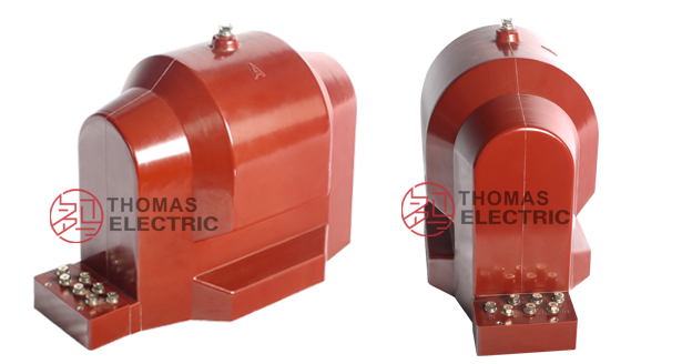
Product Show
9-10G Indoor Single-phase Epoxy Resin Voltage Transformer Thomas Electric")
JDZ9-10, JDZX(F)9-10G Single-phase Epoxy Resin VT/PTS 1
9-10G Indoor Single-phase Epoxy Resin Voltage Transformer Thomas Electric")
JDZ9-10, JDZX(F)9-10G Single-phase Epoxy Resin VT/PTS 2
Working Principle
Operating on Faraday’s law of electromagnetic induction, the voltage transformer features a high-permeability magnetic core with primary winding connected to the system voltage and secondary windings providing proportional reduced voltage. The epoxy resin encapsulation provides mechanical support and superior dielectric strength for long-term service. The dual-winding configuration allows independent metering and protection circuits.
System Application Position
- Medium Voltage Distribution: 6-10kV switchgear and distribution panels
- Energy Metering: Revenue-grade voltage measurement for billing and monitoring
- Protection Circuits: Undervoltage, overvoltage, and phase-unbalance protection schemes
- SCADA Integration: Voltage monitoring and supervisory control systems
- Residual Voltage Detection: JDZX(F) variant provides earth fault indication capability
Structural Overview
Epoxy resin cast construction with fully-enclosed design ensures superior insulation performance, moisture resistance, and mechanical strength. The post-type (pillar) mounting configuration provides compact installation in constrained switchgear environments while maintaining excellent electrical clearance and creepage distances. The secondary terminal box features dual-side cable entry for flexible wiring arrangements.
Model Designation
9-10G Indoor Single-phase Epoxy Resin Voltage Transformer Thomas Electric")
Model Code Explanation
- J — Voltage transformer (VT/PT)
- D — Single-phase configuration
- Z — Indoor support (pillar) type
- X — With residual voltage winding (earth fault detection)
- (F) — Variant designation
- 9 — Design code
- 10 — Voltage class (kV)
- G — Enhanced or modified variant
Configuration Differences
The JDZ9-10 provides basic dual-winding voltage transformation for metering and protection. The JDZX(F)9-10G adds a third winding (residual voltage winding) configured to detect earth faults and unbalanced conditions in the distribution system. Both models are electrically compatible when specified with the same ratio, accuracy classes, and burdens; selection depends on whether earth fault detection capability is required by the protection scheme.
Service Conditions
The JDZ9-10 / JDZX(F)9-10G series voltage transformers are designed for indoor operation under normal service conditions in medium-voltage power systems.
- Installation environment: Indoor installation only
- Altitude: Not exceeding 1000 m above sea level (high-altitude variants available upon request)
- Ambient temperature: −5 °C to +40 °C
- Relative humidity: ≤ 85% at +20 °C reference temperature
- Pollution degree: Class II or Class III per IEC 60664
- Environmental conditions: Free from corrosive gases, dust, or explosive/flammable media; no severe vibration or mechanical shock
- Rated frequency: 50 Hz (60 Hz available upon request)
Construction
Construction Design
- Structure: Post-type (pillar) support for indoor switchgear mounting
- Insulation: Fully enclosed epoxy resin cast construction
- Core: High-permeability silicon steel magnetic core
- Windings: Dual secondary windings (JDZ9-10) or triple windings with residual voltage output (JDZX(F)9-10G)
- Terminal box: Integrated secondary terminal enclosure with dual-side cable entry
- Mounting: Base plate with four bolt holes for secure installation
The epoxy resin casting provides stable insulation properties and resistance to moisture, contamination, UV radiation, and thermal cycling for long-term indoor service. The construction is maintenance-free apart from periodic surface cleaning.
Windings & Terminal Marking
9-10G Indoor Single-phase Epoxy Resin Voltage Transformer Thomas Electric")
- Primary terminals: A / X (or marked per project specification)
- Secondary terminals (Metering winding): a1 / x1 (or designated per specification)
- Secondary terminals (Protection winding): a2 / x2 (or designated per specification)
- Residual voltage terminals (JDZX(F) only): da / dn (open delta connection for earth fault detection)
Terminal markings follow standard VT polarity conventions. Under normal operating conditions, when primary terminal A is positive relative to X, secondary terminal a is positive relative to x. Correct terminal identification shall be observed to ensure metering and protection performance.
Technical Data
This section provides selection-oriented technical data for the JDZ9-10 / JDZX(F)9-10G series indoor, epoxy resin cast voltage transformer used in 6-10 kV class AC systems (50 Hz or 60 Hz). Data shown below is intended for preliminary selection of voltage ratio, accuracy class combinations, and rated burdens.
Definitions: Accuracy class combination indicates available metering/protection windings in one VT (dual-winding or triple-winding with residual voltage). Rated output (VA) is specified per secondary winding. Voltage factor indicates permissible continuous overvoltage per IEC 61869-3.
Notation: Secondary voltage is typically 100 V (line-to-ground) or 100/√3 V depending on primary connection. Acceptance shall be based on nameplate values and factory test report.
Data Reference
| Type | Rated Voltage Ratio (V) |
Accuracy Clas & Rated Output (VA) |
Limit Output (VA) |
Rated Insulation Level (kV) |
|||
|---|---|---|---|---|---|---|---|
| 0.2 | 0.5 | 1 | 6P | ||||
| JDZ9-10 | 10000/100 | 30 | 100 | 200 | 600 | 12/42/75 | |
| JDZ9-6 | 6000/100 | 7.2/32/60 | |||||
| JDZ9-3 | 3000/100 | 3.6/25/40 | |||||
| JDZF9-10 | 10000/100/100 | 20 | 20 | 80 | 2 × 300 | 12/42/75 | |
| JDZF9-6 | 6000/100/100 | 7.2/32/60 | |||||
| JDZF9-3 | 3000/100/100 | 3.6/25/40 | |||||
| JDZX9-10G | 10000/√3/100/√3/100/3 | 20 | 30 | 100 | 100 | 500 | 12/42/75 |
| JDZX9-6G | 6000/√3/100/√3/100/3 | 7.2/32/60 | |||||
| JDZX9-3G | 3000/√3/100/√3/100/3 | 3.6/25/40 | |||||
Additional Performance Parameters
| Parameter | Specification |
|---|---|
| Burden power factor | cosφ = 0.8 (lagging) |
| Creepage distance | Per pollution degree Class II or III (IEC 60664) |
| Partial discharge level | Per GB 1207-1997 where specified by project |
| Residual voltage winding (JDZX(F) only) | Open delta configuration, 100 V nominal output under earth fault condition |
Standards & Normative References
| Standard | Title | Application |
|---|---|---|
| IEC 61869-3 | Instrument Transformers – Part 3: Additional Requirements for Inductive Voltage Transformers | VT-specific requirements |
| GB/T 20840.3 | Instrument Transformers – Part 3: Voltage Transformers | National standard (aligned with IEC 61869 framework) |
| GB 1207-1997 | Electromagnetic Voltage Transformers | National VT standard where specified by the project |
| JB/T 2893 | Cast Resin Dry-Type Transformers | Cast resin insulation construction requirements |
| IEC 60664 | Insulation Coordination for Equipment Within Low-Voltage Systems | Pollution degree and creepage distance requirements |
| IEC 60085 | Electrical Insulation – Thermal Evaluation | Insulation thermal evaluation reference |
Factory Test Compliance
- Routine tests per applicable IEC/GB requirements (including polarity/marking, ratio verification, and accuracy verification per specified class and burden)
- Dielectric tests per insulation coordination requirements and applicable standard
- Partial discharge test where specified by the project requirement (per GB 1207-1997)
- Voltage factor test to verify continuous overvoltage capability
- Visual and dimensional inspection including marking and workmanship conformity
- Type and special tests as required by the project specification
Installation & Dimensions
- Outline dimensions and mounting details are provided in the dimensional drawings
- The transformer shall be securely mounted using the four base plate bolt holes
- Primary connection terminals may vary by variant and switchgear requirements
- Secondary wiring is accessed through the terminal box with dual-side cable entry provisions
- Adequate clearance shall be maintained for insulation, heat dissipation, and maintenance access
- Grounding provisions shall comply with applicable safety standards
Outline
9-10G Indoor Single-phase Epoxy Resin Voltage Transformer Thomas Electric")
JDZ9-10G voltage transformers outline and installation
Dimensional Reference
9-10G Indoor Single-phase Epoxy Resin Voltage Transformer Thomas Electric")
JDZ9-3, JDZ9-6, JDZ9-10 Type voltage transformers
9-10G Indoor Single-phase Epoxy Resin Voltage Transformer Thomas Electric")
JDZX9-3, JDZX9-6, JDZX9-10 Type voltage transformers
Dimensional drawings and installation details shall be provided with order confirmation and final data sheet.
Ordering Information
When placing an order, the required configuration shall be specified according to the local grid requirements, applicable standards, and project technical specification. The following parameters shall be clearly stated for technical confirmation and production release:
- Model designation (JDZ9-10 or JDZX(F)9-10G)
- Rated primary voltage and connection type (phase-to-ground or phase-to-phase)
- Rated secondary voltage (typically 100 V or 100/√3 V)
- Application and accuracy requirements (metering and/or protection accuracy class combination)
- Rated burden (VA) for each secondary winding
- Rated frequency (50 Hz or 60 Hz)
- Special requirements (altitude correction, pollution degree, partial discharge limits, etc.)
Selection Guidance
1: Determine rated primary voltage based on system nominal voltage and connection scheme (line-to-ground or line-to-line).
2: Select metering and/or protection accuracy requirements (e.g., 0.2 / 0.5 for metering; 3P for protection; or other combinations per project specification).
3: Confirm rated burden (VA) for each secondary winding based on connected meters, relays, wiring losses, and system design.
4: Specify residual voltage requirement (JDZX(F) variant) if earth fault detection is needed in the protection scheme.
If local utility or project requirements apply (e.g., enhanced insulation level, partial discharge limits, terminal arrangement, mounting configuration, documentation language, or required certificates), specify them at the ordering stage. Special configurations shall be confirmed by technical agreement and final data sheet prior to production.