Product Overview
Functional Definition
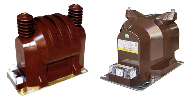
The JDZ9-20 and JDZ(X)F9-20G series, 20KV Indoor Epoxy Resin Voltage Transformers are precision electromagnetic instruments designed for accurate voltage measurement, energy metering, and relay protection applications in medium-voltage AC power systems. These transformers utilize electromagnetic induction principles to provide galvanically isolated secondary voltage signals proportional to primary voltage, enabling safe interface with metering, protection, and monitoring equipment.
Key Ratings
| Item | Specification (per order / nameplate) |
|---|---|
| System voltage class | 20 kV class (indoor switchgear and distribution applications) |
| Rated frequency | 50 Hz (60 Hz available upon request) |
| Rated primary voltage | 20 kV or 20/√3 kV (line-to-ground for grounded neutral systems) |
| Rated secondary voltage | 100 V, 100/√3 V, 100/3 V (as specified) |
| Accuracy classes | Metering and/or protection windings as specified (e.g., 0.2 / 0.5 for metering; 6P for protection) |
| Rated burden | Per winding as specified (VA) |
| Burden power factor | cosφ = 0.8 (lagging) unless otherwise specified by the project standard |
| Maximum output capacity | Per model variant (VA) |
| Insulation level | 24/65/125 kV (Um/ACSD/LI) per IEC 60071-1 |
| Applicable standards | IEC 61869-3 / IEC 61869-1; GB/T 20840.3 / 20840.1; GB 1207-2006 |
| Model variants | JDZ9-20 (single-winding), JDZF9-20 (dual-winding), JDZX9-20G (three-winding with residual voltage detection), JDZXF9-20G (four-winding with residual voltage detection) |
Working Principle
Operating on Faraday’s law of electromagnetic induction, the voltage transformer features a laminated magnetic core with primary winding connected to the high-voltage circuit and secondary windings providing proportional voltage output. The magnetic flux generated by primary voltage induces corresponding voltage in the secondary windings, delivering standardized output voltage to connected burden. The epoxy resin cast insulation system provides complete electrical isolation between primary, secondary, and tertiary windings.
System Application Position
- Medium Voltage Distribution: 20kV switchgear and distribution substations
- Energy Metering: Revenue-grade voltage measurement for billing systems
- Protection Circuits: Overvoltage, undervoltage, and ground fault protection schemes
- SCADA Integration: Voltage monitoring for supervisory control and data acquisition systems
- Power Quality Monitoring: Voltage level assessment and quality analysis
Structural Overview
Epoxy resin vacuum cast construction with fully-enclosed design ensures superior insulation performance, moisture resistance, and mechanical strength. The support-type mounting configuration provides compact installation in indoor switchgear environments while maintaining excellent electrical clearance and creepage distances. Multiple secondary winding configurations enable simultaneous metering, protection, and residual voltage detection functions.
Model Designation
F9-20G 20KV Indoor Epoxy Resin Voltage Transformer Thomas Electric")
Model Code Explanation
- J — Voltage transformer (VT)
- D — Single-phase design
- Z — Cast-resin (epoxy) insulated, fully enclosed structure
- 9 — Design code (platform/iteration)
- 20 — Voltage class (kV)
- F (where present) — Dual secondary winding configuration (two independent metering/protection cores)
- X (where present) — Includes open-delta tertiary winding for residual voltage (ground fault) detection
- G (where present) — Grounded neutral system application (20/√3 kV primary rating)
Model Variant Overview
| Model | Primary
Voltage Rating |
Secondary
Configuration |
Application |
|---|---|---|---|
| JDZ9-20 | 20 kV
(phase-to-phase) |
Single secondary winding:
100 V or 100/√3/100/3 V |
Basic metering or protection
(isolated neutral systems) |
| JDZF9-20 | 20 kV
(phase-to-phase) |
Dual secondary windings: 100/100 V | Independent metering and protection
(isolated neutral systems) |
| JDZX9-20G | 20/√3 kV
(phase-to-ground) |
Single secondary + residual voltage winding: 100/√3 V + 100/3 V | Metering/protection + ground fault detection
(grounded neutral systems) |
| JDZXF9-20G | 20/√3 kV
(phase-to-ground) |
Dual secondary + residual voltage winding: 100/√3 V + 100/√3 V + 100/3 V | Independent metering/protection + ground fault detection
(grounded neutral systems) |
Service Conditions
The JDZ9-20 series voltage transformers are designed for indoor operation under normal service conditions in medium-voltage power systems.
- Installation environment: Indoor installation only
- Altitude: Not exceeding 1000 m above sea level (higher altitude shall be specified for engineering confirmation and derating)
- Ambient temperature: −5 °C to +40 °C
- Relative humidity: ≤ 95% (non-condensing at +20 °C reference)
- Pollution degree: Class II per IEC 60664-1
- Installation position: Vertical mounting on switchgear base or panel
- Environmental conditions: Free from corrosive gases, explosive or flammable media, severe vibration, mechanical shock, or impact
Construction
Construction Design
- Structure: Support (post) type for indoor switchgear mounting
- Insulation: Fully enclosed epoxy resin vacuum cast insulation system
- Core: High-grade silicon steel laminated core with low loss characteristics
- Windings: Primary winding rated for full insulation level; secondary windings with independent cores where multi-winding configuration applies
- System: Integrated primary and secondary insulation system with dedicated tertiary winding for residual voltage detection (X-type models)
The epoxy resin vacuum casting provides stable insulation properties and resistance to moisture, contamination, thermal aging, and UV degradation for long-term indoor service. The fully-enclosed construction eliminates external contamination risks and provides inherent tracking resistance.
Windings & Terminal Marking
JDZ9-20 / JDZF9-20 (Isolated Neutral System Models)
- Primary terminals: A / X (high-voltage input/output)
- Secondary terminals (Group 1): a / x (metering or protection winding)
- Secondary terminals (Group 2, JDZF9-20): a’ / x’ (second metering or protection winding)
JDZX9-20G / JDZXF9-20G (Grounded Neutral System Models)
- Primary terminals: A / N (high-voltage phase and neutral connection)
- Secondary terminals (Group 1): a / n (metering or protection winding)
- Secondary terminals (Group 2, JDZXF9-20G): a’ / n’ (second metering or protection winding)
- Tertiary terminals (residual voltage winding): da / dn (open-delta residual voltage detection)
Terminal markings follow standard VT polarity conventions per IEC 61869-3. Under normal operating conditions, terminal A is connected to the phase conductor. For grounded systems, terminal N shall be connected to system neutral. Correct terminal identification shall be observed to ensure metering and protection performance.
Technical Data
This section provides selection-oriented technical data for the JDZ9-20 series indoor, cast-resin voltage transformers used in 20 kV class AC systems (50 Hz). Data shown below is intended for preliminary selection of model variant, accuracy class combinations, rated burdens, and output capacity.
Definitions: Accuracy class combination indicates available metering/protection windings in one VT (multi-winding configuration may apply). Rated output (VA) is specified per secondary winding. Maximum output (VA) represents the thermal limit for continuous operation. Insulation level is expressed as Um/ACSD/LI (maximum system voltage / short-duration AC withstand / lightning impulse withstand) per IEC 60071-1.
Notation: Voltage ratios shown are primary/secondary for single-phase connection. For three-phase systems with grounded neutral (G-type models), rated primary voltage is 20/√3 kV (phase-to-ground). Residual voltage winding output is 100/3 V under normal balanced conditions and increases under ground fault conditions.
Data Reference
| Model | Rated Voltage Ratio (V) |
Accuracy Class Combination |
Rated Output (VA) |
Maximum Output (VA) |
Insulation Level (kV) Um / ACSD / LI |
|---|---|---|---|---|---|
| JDZ9-20 | 20000/100 or 20000/100/√3/100/3 |
0.2 | 20 | 600 | 24 / 65 / 125 |
| 0.5 | 50 | 600 | |||
| JDZF9-20 | 20000/100/100 | 0.2 / 0.5 | 20 / 20 | 2 × 300 | |
| 0.2 / 0.5 | 20 / 30 | 2 × 300 | |||
| 0.5 / 0.5 | 30 / 30 | 2 × 300 | |||
| JDZX9-20G | 20000/√3 / 100/√3 / 100/3 | 0.2 / 6P | 20 / 100 | 600 | |
| 0.5 / 6P | 50 / 100 | 600 | |||
| JDZXF9-20G | 20000/√3 / 100/√3 / 100/√3 / 100/3 | 0.2 / 0.2 / 6P | 20 / 20 / 100 | 2 × 300 | |
| 0.2 / 0.5 / 6P | 20 / 30 / 100 | 2 × 300 | |||
| 0.5 / 0.5 / 6P | 30 / 30 / 100 | 2 × 300 |
Standards & Normative References
| Standard | Title | Application |
|---|---|---|
| IEC 61869-1 | Instrument Transformers – Part 1: General Requirements | General requirements |
| IEC 61869-3 | Instrument Transformers – Part 3: Additional Requirements for Inductive Voltage Transformers | VT-specific requirements |
| GB/T 20840.1 | Instrument Transformers – Part 1: General Requirements | National standard (aligned with IEC 61869 framework) |
| GB/T 20840.3 | Instrument Transformers – Part 3: Inductive Voltage Transformers | National VT requirements (aligned with IEC 61869-3) |
| GB 1207-2006 | Electromagnetic Voltage Transformers | National VT standard where specified by the project |
| IEC 60071-1 | Insulation Co-ordination – Part 1: Definitions, Principles and Rules | Insulation level coordination |
| IEC 60664-1 | Insulation Coordination for Equipment within Low-Voltage Systems | Pollution degree and clearance requirements |
| IEEE C57.13 | Standard Requirements for Instrument Transformers | Optional (North America project reference) |
| IEC 60085 | Electrical Insulation – Thermal Evaluation and Designation | Insulation thermal class evaluation reference |
Factory Test Compliance
- Routine tests per applicable IEC/GB requirements (including polarity/marking verification, voltage ratio verification, and accuracy verification per specified class and burden)
- Dielectric tests per insulation coordination requirements and applicable standard (power-frequency withstand test and lightning impulse withstand test)
- Partial discharge test where specified by the project requirement
- Visual and dimensional inspection including marking and workmanship conformity
- Temperature rise test at rated output and maximum output conditions
- Type and special tests as required by the project specification
Installation & Dimensions
Outline
F9-20G 20KV Indoor Epoxy Resin Voltage Transformer Thomas Electric")
F9-20G 20KV Indoor Epoxy Resin Voltage Transformer Thomas Electric")
Wiring schematic diagram
- Outline dimensions and mounting details are provided in the dimensional drawings specific to each model variant.
- The transformer shall be securely mounted using the designated fixing holes on the mounting base.
- Primary terminals shall be connected to high-voltage buswork with appropriate clearances and creepage distances per applicable standards.
- Adequate clearance shall be maintained for insulation, heat dissipation, and maintenance access.
- For grounded neutral system applications (G-type models), verify correct primary terminal connection (A to phase, N to neutral).
Installation Requirements
- Mounting orientation: Vertical installation with primary terminals at top
- Clearances: Maintain minimum phase-to-phase and phase-to-ground clearances per IEC 60071-1 and local electrical code
- Terminal access: Ensure secondary terminal compartments are accessible for wiring and maintenance
- Ventilation: Provide adequate air circulation for heat dissipation under continuous rated load
- Environmental protection: Protect from direct water exposure, condensation, and excessive dust accumulation
Ordering Information
When placing an order, the required configuration shall be specified according to the system grounding configuration, applicable standards, and project technical specification. The following parameters shall be clearly stated for technical confirmation and production release:
- Model designation (JDZ9-20 / JDZF9-20 / JDZX9-20G / JDZXF9-20G)
- Rated primary voltage (20 kV for isolated neutral; 20/√3 kV for grounded neutral)
- Rated secondary voltage (100 V, 100/√3 V, 100/3 V as applicable)
- System frequency (50 Hz or 60 Hz)
- Accuracy class combination (metering and/or protection accuracy class per secondary winding)
- Rated burden (VA) for each secondary winding
- Quantity (single-phase units required; typically 3 units for three-phase system)
Selection Guidance
Step 1: Determine system grounding configuration (isolated neutral vs. grounded neutral) and select appropriate model family (JDZ/JDZF for isolated; JDZX/JDZXF for grounded with residual voltage detection).
Step 2: Determine if independent metering and protection windings are required (single-winding: JDZ/JDZX; dual-winding: JDZF/JDZXF).
Step 3: Select metering and/or protection accuracy requirements (e.g., 0.2 for high-precision revenue metering; 0.5 for instrumentation; 6P for protection relays).
Step 4: Calculate rated burden (VA) for each secondary circuit based on connected meters/relays/instruments and wiring losses at rated secondary voltage.
Step 5: Verify insulation level (24/65/125 kV) is suitable for the system maximum voltage and environmental conditions.
Step 6: For three-phase systems, specify quantity (typically 3 single-phase units). For residual voltage detection, ensure correct open-delta connection configuration.
If local utility or project requirements apply (e.g., enhanced insulation level, special accuracy classes, custom voltage ratios, VT fuse coordination, terminal arrangement, mounting constraints, documentation language, or required certificates), specify them at the ordering stage. Special configurations shall be confirmed by technical agreement and final data sheet prior to production.