Product Overview
The JDZC-3/6/10 series single-phase epoxy resin voltage transformers are precision electromagnetic instruments designed for accurate voltage measurement, energy metering, control circuits, and relay protection in medium-voltage AC power systems. Based on electromagnetic induction principles, these voltage transformers provide galvanically isolated secondary voltage signals proportional to the primary voltage, suitable for 3–10 kV indoor distribution applications.
Key Ratings
The table below summarizes the principal electrical ratings and insulation parameters of the JDZC-3/6/10 series voltage transformers. Final values are subject to order specification and nameplate data.
| Item | Specification (per order / nameplate) |
|---|---|
| System voltage class | 3 kV / 6 kV / 10 kV class (indoor distribution applications) |
| Rated frequency | 50 Hz (60 Hz available upon request) |
| Rated voltage ratio | 3000/100/220 V, 6000/100/220 V, 10000/100/220 V |
| Accuracy classes | 0.2 or 0.5 for metering applications |
| Rated output | 30-1500 VA per accuracy class as specified |
| Maximum output capacity | 600-3000 VA depending on configuration |
| Insulation level | JDZC-3: 3.6/25/40 kV (Um/Ud/Up) JDZC-6: 7.2/32/60 kV JDZC-10: 12/42/75 kV |
| Applicable standards | GB/T 208-2007; IEC 61869-3 (reference) |
| Creepage distance grade | Grade II pollution environment |
Working Principle
Operating on Faraday’s law of electromagnetic induction, the voltage transformer features a laminated magnetic core with the primary winding connected to the system voltage and secondary windings wound around the core. The alternating magnetic flux generated by the primary voltage induces a proportional voltage in the secondary winding, delivering standardized output voltage to connected metering, protection, and control burdens.
System Application Position
- Medium Voltage Distribution: 3-10kV switchgear and distribution panels
- Energy Metering: Revenue-grade electricity measurement systems
- Protection Circuits: Overvoltage, undervoltage, and ground fault protection schemes
- Control Circuits: Voltage signal for control and monitoring systems
- Operating Power Supply: Auxiliary power for control devices when configured accordingly
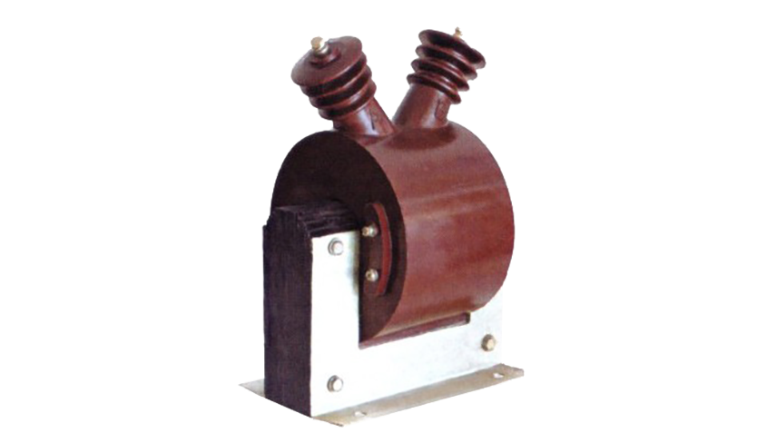
Structural Overview
The epoxy resin cast construction with semi-enclosed design ensures reliable insulation performance, moisture resistance, and mechanical strength. The compact mounting configuration supports secure installation in indoor switchgear environments while maintaining required electrical clearance and creepage distances for Grade II pollution conditions.
Model Designation

Model Code Explanation
- J — Voltage transformer (VT)
- D — Single-phase configuration
- Z — Cast-resin (epoxy) insulated structure
- C — Semi-enclosed design
- 3 / 6 / 10 — Voltage class (kV)
This designation system enables clear identification of insulation structure, enclosure type, and voltage class for engineering selection.
Service Conditions
The JDZC-3/6/10 series voltage transformers are designed for indoor operation under normal service conditions in medium-voltage power systems.
- Installation environment: Indoor installation only
- Altitude: Not exceeding 1000 m above sea level (higher altitude shall be specified for engineering confirmation)
- Ambient temperature: −5 °C to +40 °C
- Relative humidity: ≤ 85%
- Creepage distance grade: Grade II pollution environment
- Environmental conditions: Free from corrosive gases or vapors; free from explosive or flammable media; no severe vibration, mechanical shock, or impact
Construction
Construction Design
- Structure: Semi-enclosed type for indoor switchgear
- Insulation: Epoxy resin cast insulation system
- Core: Laminated silicon steel core design
- System: Integrated primary and secondary winding system
- Terminals: Primary terminals positioned at top of housing
The epoxy resin casting provides stable insulation properties and resistance to moisture, contamination, and aging for long-term indoor service.
Windings & Terminal Marking
- Primary terminals: A / X (or U / N for phase notation)
- Secondary terminals (Measurement winding): a / x (or u / n)
- Auxiliary secondary terminals (where applicable): ad / xd (or ud / nd)
Terminal markings follow standard VT polarity conventions. Under normal operating conditions, when primary terminal A is positive with respect to X, secondary terminal a is positive with respect to x. Correct terminal identification shall be observed to ensure metering and protection performance.
Technical Data
This section provides selection-oriented technical data for the JDZC-3/6/10 series single-phase, semi-enclosed epoxy resin voltage transformers used in 3–10 kV class AC systems operating at 50 Hz. The data supports preliminary selection of accuracy class, rated output capacity, and insulation coordination.
Definitions: Accuracy class indicates measurement precision (0.2 or 0.5 class). Rated output (VA) is specified per accuracy class. Maximum output is the total burden capacity the transformer can support. Insulation level is expressed as Um/Ud/Up (maximum system voltage / power-frequency withstand voltage / lightning impulse withstand voltage).
Data Reference
| Model | Rated Voltage Ratio (V) |
Accuracy Class Rated Output (VA) |
Maximum Output (VA) |
Rated Insulation Level (kV) Um/Ud/Up |
|---|---|---|---|---|
| JDZC-3/6/10 | 3000/100/220 6000/100/220 10000/100/220 |
0.2 class: 30 VA 0.5 class: 300 VA |
600 | 3.6/25/40 7.2/32/60 12/42/75 |
| 0.2 class: 30 VA 0.5 class: 400 VA |
800 | |||
| 0.2 class: 30 VA 0.5 class: 500 VA |
1000 | |||
| 0.2 class: 30 VA 0.5 class: 600 VA |
1200 | |||
| 0.2 class: 30 VA 0.5 class: 800 VA |
1500 | |||
| 0.2 class: 30 VA 0.5 class: 1000 VA |
2000 | |||
| 0.2 class: 30 VA 0.5 class: 1500 VA |
3000 |
Standards & Normative References
| Standard | Title | Application |
|---|---|---|
| GB/T 208-2007 | Voltage Transformers | Primary national standard for VT requirements |
| IEC 61869-1 | Instrument Transformers – Part 1: General Requirements | General requirements (reference) |
| IEC 61869-3 | Instrument Transformers – Part 3: Additional Requirements for Voltage Transformers | VT-specific requirements (reference) |
| GB 311.1 | Insulation Co-ordination | Insulation level coordination |
| DL/T 596 | Electric Power Equipment Preventive Test Procedures | Routine and preventive testing procedures |
Factory Test Compliance
- Routine tests per GB/T 208-2007 requirements (including polarity/marking verification, ratio verification, and accuracy verification per specified class and burden)
- Dielectric tests per insulation coordination requirements and applicable standard
- Partial discharge test where specified by the project requirement
- Visual and dimensional inspection including marking and workmanship conformity
- Type and special tests as required by the project specification
Installation & Dimensions
- Outline dimensions and mounting details are provided in the dimensional drawings.
- The transformer shall be securely mounted using the designated fixing holes on the base.
- Primary connections shall be made at the top terminals following proper torque specifications.
- Adequate clearance shall be maintained for insulation, heat dissipation, and maintenance access.
- Ensure proper grounding of the transformer core and secondary circuit per applicable safety standards.
Outlines

JDZC Voltage Transformers 600A

JDZC Voltage Transformers 800-1200 VA

JDZC Voltage Transformers 1500-2000 VA

JDZC Voltage Transformers 2000-2500 VA
Dimensional drawings showing mounting dimensions, terminal positions, and clearance requirements shall be provided in the product-specific documentation.
Connection Diagrams

Safety Notes
- One point of the secondary circuit shall be reliably grounded in accordance with applicable standards.
- Do not exceed the maximum rated output (VA) to prevent overheating and accuracy degradation.
- Primary terminals are live and shall be treated with appropriate electrical safety precautions.
- All installation and maintenance work shall comply with local electrical safety regulations.
- Ferroresonance conditions shall be avoided through appropriate circuit design, grounding practice, and capacitance control.
Ordering Information
When placing an order, the required configuration shall be specified according to the local grid requirements, applicable standards, and project technical specification. The following parameters shall be clearly stated for technical confirmation and production release:
- Model designation (JDZC-3, JDZC-6, or JDZC-10)
- Rated voltage ratio (e.g., 10000/100/220 V)
- Accuracy class requirements (0.2 or 0.5 for metering applications)
- Rated output (VA) for each accuracy class
- Maximum output capacity (VA)
- Insulation level (if special requirements beyond standard values)
For special requirements (partial discharge limits, terminal arrangement, mounting constraints, documentation language, or certificates), specify at ordering stage for technical agreement and final data sheet prior to production.