Product Overview
Functional Definition
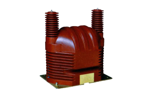
The JDZ9-35 and JDZF9-35 Outdoor epoxy resin cast voltage transformer are precision electromagnetic instruments designed for accurate voltage measurement, energy metering, voltage monitoring, and relay protection applications in 35kV medium-voltage AC outdoor power systems. These transformers utilize electromagnetic induction principles to provide galvanically isolated secondary voltage signals proportional to primary voltage.
Key Ratings
| Item | Specification (per order / nameplate) |
|---|---|
| System voltage class | 35 kV class (outdoor medium-voltage distribution applications) |
| Rated frequency | 50 Hz (60 Hz available upon request) |
| Rated primary voltage | 35000 V (line-to-ground for single-phase; line-to-line variations available) |
| Rated secondary voltage | 100 V or 220 V (line-to-ground); 100/√3 V (for grounded wye configurations) |
| Accuracy classes | Metering and/or monitoring/protection cores as specified (e.g., 0.2, 0.5, 6P) |
| Rated burden | Per core/winding as specified (20-90 VA depending on configuration) |
| Burden power factor | cosφ = 0.8 (lagging) unless otherwise specified by the project standard |
| Maximum output capacity | 300-800 VA depending on model variant |
| Insulation level | 40.5 / 95 / 200 kV (Um / LIWL / ACWL) |
| Applicable standards | IEC 61869-3; GB/T 20840.1 / 20840.3; GB 1207-2006 |
| Model variants | JDZ9-35 / JDZF9-35 / JDZX9-35G / JDZXF9-35G |
Working Principle
Operating on Faraday’s law of electromagnetic induction, the voltage transformer features a laminated magnetic core with primary winding connected to system voltage and secondary windings wound around the core. The alternating magnetic flux generated by primary voltage induces proportional voltage in the secondary winding, delivering standardized output voltage through connected burden. The transformer operates in low magnetic flux density region to ensure linearity and accuracy across the specified voltage range.
System Application Position
- Medium Voltage Distribution: 35kV outdoor substations and distribution networks
- Energy Metering: Revenue-grade voltage measurement systems for billing applications
- Voltage Monitoring: System voltage supervision and power quality monitoring
- Protection Circuits: Overvoltage, undervoltage, and directional protection schemes
- SCADA Integration: Supervisory control and data acquisition systems
Structural Overview
Epoxy resin cast construction with fully-enclosed design ensures superior insulation performance, UV resistance, moisture resistance, and mechanical strength. The outdoor post-type mounting configuration provides reliable installation in substation environments while maintaining excellent electrical clearance and creepage distances suitable for II-grade pollution environments.
Model Designation
 Thomas Electric")
Model Code Explanation
- J — Voltage transformer (VT)
- D — Single-phase configuration
- Z — Cast-resin (epoxy) insulated, fully enclosed structure
- F — Dual secondary windings (when present)
- X — With tertiary winding for open-delta protection (when present)
- 9 — Design code (platform/iteration)
- 35 — Voltage class (kV)
- G — Grounding application variant (when present)
Variant Differences
| Model | Secondary Windings | Typical Application |
|---|---|---|
| JDZ9-35 | Single secondary winding | Single-purpose metering or monitoring |
| JDZF9-35 | Dual secondary windings | Separate metering and monitoring/protection cores |
| JDZX9-35G | Dual windings + tertiary winding | Metering, monitoring, and ground fault/open-delta protection |
| JDZXF9-35G | Three secondary windings | Metering, monitoring, and dedicated protection core |
JDZ9-35 and JDZF9-35 variants are electrically compatible when specified with the same voltage ratio, accuracy classes, and burdens. The F-series provides dual independent secondary windings for simultaneous metering and monitoring applications without burden interaction.
Service Conditions
The JDZ9-35/JDZF9-35 series voltage transformers are designed for outdoor operation under normal service conditions in 35kV medium-voltage power systems.
- Installation environment: Outdoor installation (post-mounted in substations)
- Altitude: Not exceeding 1000 m above sea level (higher altitude shall be specified for engineering confirmation)
- Ambient temperature: −25 °C to +40 °C (daily average ≤ 30 °C)
- Relative humidity: Daily average ≤ 95%, monthly average ≤ 90%
- Pollution grade: Grade II (suitable for areas without severe industrial contamination)
- Environmental conditions: No severe corrosive gases, explosive or flammable media; no abnormal vibration or mechanical shock
- UV and weather resistance: Epoxy resin structure provides excellent UV resistance and weathering protection
Construction
Construction Design
- Structure: Outdoor post-type for substation installation
- Insulation: Fully enclosed epoxy resin cast insulation with integrated structure
- Core: Silicon steel laminated core design optimized for low flux density operation
- System: Integrated primary and multi-secondary insulation system
- Mounting: Bottom-mounted flange with fixing bolt holes
- Protection: Optional lightning arrester (zinc oxide) integration available
The epoxy resin casting provides stable insulation properties and resistance to moisture, UV radiation, contamination, and aging for long-term outdoor service in various climatic conditions.
Windings & Terminal Marking
- Primary terminals: A / X (high-voltage terminals)
- Secondary terminals (Winding 1): a / x or a1 / x1
- Secondary terminals (Winding 2): a2 / x2 (JDZF series)
- Tertiary terminals (Open-delta): ad / xd (JDZX series)
Terminal markings follow standard VT polarity conventions per IEC 61869-3 and GB/T 20840.3. Under normal operating conditions, when primary terminal A is instantaneously positive with respect to X, secondary terminal a is instantaneously positive with respect to x. Correct terminal identification shall be observed to ensure metering and protection performance.
Technical Data
This section provides selection-oriented technical data for the JDZ9-35 and JDZF9-35 series outdoor, cast-resin voltage transformers used in 35 kV class AC systems (50 Hz standard, 60 Hz available). Data shown below is intended for preliminary selection of accuracy class combinations, rated burdens, and maximum output capacity.
Definitions: Accuracy class combination indicates available metering/monitoring/protection cores in one VT (multi-core configuration may apply). Rated output (VA) is specified per secondary winding. Maximum output (VA) represents the thermal capacity limit of each winding. Insulation level is specified as Um / LIWL / ACWL where Um = maximum system voltage, LIWL = lightning impulse withstand level, ACWL = AC withstand level.
Notation: Voltage ratios expressed as primary/secondary. For grounded wye systems, line-to-ground voltages apply; divide by √3 where indicated. Acceptance shall be based on nameplate values and factory test report.
Data Reference
| Model | Rated Voltage Ratio (V) |
Accuracy Class Combination |
Rated Output (VA) |
Maximum Output (VA) |
Insulation Level (kV) Um / LIWL / ACWL |
|---|---|---|---|---|---|
| JDZ9-35 | 35000 / 100 35000 / 220 |
0.2 | 50 | 800 | 40.5 / 95 / 200 |
| JDZ9-35 | 35000 / 100 35000 / 220 |
0.5 | 90 | 800 | 40.5 / 95 / 200 |
| JDZF9-35 | 35000 / 100 / 100 35000 / 100 / 220 |
0.2 / 0.2 | 30/30, 30/50, 50/50 | 2 × 400 | 40.5 / 95 / 200 |
| JDZF9-35 | 35000 / 100 / 100 35000 / 100 / 220 |
0.2 / 0.5 | 30/30, 30/50, 50/50 | 2 × 400 | 40.5 / 95 / 200 |
| JDZF9-35 | 35000 / 100 / 100 35000 / 100 / 220 |
0.5 / 0.5 | 30/30, 30/50, 50/50 | 2 × 400 | 40.5 / 95 / 200 |
| JDZX9-35G | 35kV/√3 / 100/√3 / 100/3 | 0.2 / 6P | 30 / 100 | 600 | 40.5 / 95 / 200 |
| JDZX9-35G | 35kV/√3 / 100/√3 / 100/3 | 0.5 / 6P | 90 / 100 | 600 | 40.5 / 95 / 200 |
| JDZXF9-35G | 35kV/√3 / 100/√3 / 100/√3 / 100/3 | 0.2 / 0.2 / 6P | 20/20/100 | 2 × 300 + 100 | 40.5 / 95 / 200 |
| JDZXF9-35G | 35kV/√3 / 100/√3 / 100/√3 / 100/3 | 0.2 / 0.5 / 6P | 25/25/100 | 2 × 300 + 100 | 40.5 / 95 / 200 |
| JDZXF9-35G | 35kV/√3 / 100/√3 / 100/√3 / 100/3 | 0.5 / 0.5 / 6P | 30/30/100 | 2 × 300 + 100 | 40.5 / 95 / 200 |
Standards & Normative References
| Standard | Title | Application |
|---|---|---|
| IEC 61869-3 | Instrument Transformers – Part 3: Additional Requirements for Voltage Transformers | VT-specific requirements |
| IEC 61869-1 | Instrument Transformers – Part 1: General Requirements | General requirements |
| GB/T 20840.3 | Instrument Transformers – Part 3: Voltage Transformers | National VT standard (aligned with IEC 61869-3) |
| GB/T 20840.1 | Instrument Transformers – Part 1: General Requirements | National general requirements (aligned with IEC 61869-1) |
| GB 1207-2006 | Voltage Transformers | National VT standard where specified by the project |
| GB/T 22071.1 | Insulation Coordination for Medium-Voltage Equipment | Insulation level verification |
| IEC 60071-1 | Insulation Co-ordination – Part 1: Definitions, Principles and Rules | Insulation coordination reference |
| GB/T 16927.1 | High-voltage Test Techniques – Part 1: General Definitions and Test Requirements | Dielectric testing requirements |
| IEC 60060-1 | High-voltage Test Techniques – Part 1: General Definitions and Test Requirements | International dielectric test reference |
Factory Test Compliance
- Routine tests per applicable IEC/GB requirements (including polarity/marking verification, ratio verification, voltage error and phase displacement verification per specified accuracy class and burden)
- Dielectric tests per insulation coordination requirements:
- Power frequency withstand test (ACWL): 200 kV for 1 minute
- Lightning impulse withstand test (LIWL): 95 kV (positive and negative)
- Partial discharge test per GB/T 20840.1-2010 and GB/T 20840.3-2013 requirements (≤10 pC at 1.2 Um)
- Temperature rise test under rated burden to verify thermal performance
- Visual and dimensional inspection including marking, workmanship conformity, and installation interface verification
- Type and special tests as required by the project specification
Installation & Dimensions
- Outline dimensions and mounting details are provided in the dimensional drawings.
- The transformer shall be securely mounted using the bottom flange fixing holes with appropriate hardware.
- Primary connection is made via high-voltage busbar or terminal connector at terminal A.
- Terminal X must be properly grounded per system grounding practice.
- Adequate clearance shall be maintained for insulation coordination, heat dissipation, and maintenance access.
- Lightning protection (surge arrester) shall be installed per project requirements.
Outline Drawings
 Thomas Electric")
JDZ9-35 / JDZF9-35
Wiring Diagram
 Thomas Electric")
Connection Schematic
Safety Notes
- Secondary circuit must have one point reliably grounded (typically terminal x or x1) to ensure personnel safety and proper operation.
- During inspection or maintenance, the primary circuit must be de-energized, isolated, and grounded before any work on secondary circuits.
- Fuses or circuit breakers shall be installed in secondary circuits for protection against short circuits.
- All installation and maintenance work shall comply with local electrical safety regulations and utility standards.
- Regular inspection of epoxy resin surface condition, terminal connections, and grounding integrity is recommended.
Ordering Information
When placing an order, the required configuration shall be specified according to the local grid requirements, applicable standards, and project technical specification. The following parameters shall be clearly stated for technical confirmation and production release:
- Rated primary voltage (35000 V or 35kV/√3 for grounded systems)
- Rated secondary voltage (100 V, 220 V, or 100/√3 V as applicable)
- Number of secondary windings (single, dual, or triple winding configuration)
- Application and accuracy requirements (metering and/or monitoring/protection accuracy class combination)
- Rated burden (VA) for each secondary core/winding
- Insulation level requirements (standard or enhanced for high-altitude/pollution)
- Frequency (50 Hz standard; 60 Hz if required)
- Special features (if any): lightning arrester integration, enhanced UV protection, special mounting arrangements
If local utility or project requirements apply (e.g., enhanced insulation level, specific partial discharge limits, terminal arrangement, auxiliary equipment integration, mounting constraints, documentation language, or required certificates), specify them at the ordering stage. Special configurations shall be confirmed by technical agreement and final datasheet prior to production.