Product Overview
Functional Definition
The JDZW-35, JDZ(X)FW-35 series voltage transformers are precision electromagnetic instruments designed for accurate voltage measurement, energy metering, and relay protection applications in 35 kV outdoor power distribution systems. These transformers utilize electromagnetic induction principles to provide galvanically isolated secondary voltage signals proportional to primary system voltage. The cast resin construction ensures reliable outdoor operation in varying environmental conditions.
Key Ratings
| Item | Specification (per order / nameplate) |
|---|---|
| System voltage class | 35 kV class (outdoor power distribution and protection applications) |
| Rated frequency | 50 Hz (60 Hz available upon request) |
| Rated primary voltage | 35000 V (line-to-line) or 35000/√3 V (line-to-neutral) |
| Rated secondary voltage | 100 V (single secondary), 100/100 V (dual secondary), 100/√3/100/3 V (triple secondary with open delta) |
| Accuracy classes | Metering and/or protection cores as specified (e.g., 0.2 / 0.5, 6P) |
| Rated burden | Per core/winding as specified (VA) |
| Burden power factor | cosφ = 0.8 (lagging) unless otherwise specified by the project standard |
| Rated output capacity | Per winding specification (30-100 VA) |
| Maximum output capacity | 400-1000 VA depending on configuration |
| Insulation level | 40.5/95/200 kV (rated voltage / lightning impulse / power-frequency withstand) |
| Applicable standards | IEC 61869-3 / IEC 61869-1; GB/T 20840.3 / 20840.1; GB 1207-2006 |
| Structural variants | JDZW-35 / JDZFW-35 / JDZXW-35 / JDZXFW-35 |
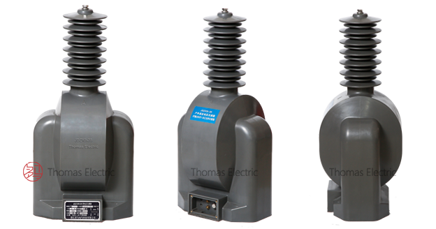
Product Shows
FW-35kV outdoor cast resin voltage transformers Thomas Electric")
Working Principle
Operating on Faraday’s law of electromagnetic induction, the voltage transformer features a laminated silicon steel core with primary winding connected to the high-voltage system and secondary windings providing standardized low-voltage output. The magnetic flux generated by primary voltage induces proportional voltage in the secondary winding, delivering standardized 100 V output signals through connected burden. The fully enclosed cast resin structure ensures stable magnetic performance and electrical insulation.
System Application Position
- 35 kV Distribution Systems: Outdoor switchgear, ring main units, and distribution substations
- Energy Metering: Revenue-grade electricity measurement for billing and monitoring
- Protection Circuits: Overvoltage, undervoltage, and differential protection schemes
- SCADA Integration: Voltage monitoring and supervisory control systems
- Synchronizing: System synchronization and phase angle measurement
Structural Overview
Fully-enclosed cast resin construction with outdoor-grade epoxy formulation ensures superior insulation performance, UV resistance, arc resistance, and moisture resistance. The post-type mounting configuration provides compact installation in outdoor switchgear environments while maintaining excellent electrical clearance and creepage distances. Advanced vacuum casting technology eliminates voids and ensures uniform insulation properties throughout the service life.
Model Designation
FW-35kV outdoor cast resin voltage transformers Thomas Electric")
Model Code Explanation
- J — Voltage transformer (VT)
- D — Single-phase configuration
- Z — Indoor/outdoor support (pillar) type
- W — Outdoor service (weather-resistant)
- F — Dual secondary windings (when present)
- X — Open delta / residual voltage detection winding (when present)
- 35 — Voltage class (kV)
Variant Differences
JDZW-35: Single secondary winding for metering or protection application
JDZFW-35: Dual secondary windings (typically one for metering, one for protection)
JDZXW-35: Triple secondary configuration with open delta winding for residual voltage detection (zero-sequence protection)
JDZXFW-35: Quad secondary configuration combining dual metering/protection windings with open delta for comprehensive system monitoring
All variants share the same core insulation structure and outdoor weatherproof design, with differences primarily in secondary winding configuration to match system protection and metering requirements.
Service Conditions
The JDZW-35 series voltage transformers are designed for outdoor operation under normal service conditions in medium-voltage power systems.
- Installation environment: Outdoor installation (weather-resistant construction)
- Altitude: Not exceeding 1000 m above sea level (higher altitude shall be specified for engineering confirmation and derating)
- Ambient temperature: −5 °C to +40 °C
- Daily average temperature: ≤ 30 °C
- Relative humidity: Daily average ≤ 95%, monthly average ≤ 90% (at +20 °C reference)
- Pollution severity: Class II or lower per IEC 60815
- Environmental conditions: Free from corrosive gases, explosive atmospheres, or severe mechanical shock
- Seismic conditions: Seismic intensity ≤ 8 per applicable regional standard
Construction
Construction Design
- Structure: Support (post) type for outdoor power distribution equipment
- Insulation: Fully enclosed outdoor-grade epoxy resin cast insulation
- Core: Laminated cold-rolled silicon steel with optimized magnetic circuit
- Casting technology: Vacuum pressure gelation (VPG) process
- UV resistance: Outdoor-grade epoxy formulation with UV stabilizers
- Arc resistance: High-temperature resistant epoxy compound
- Aging resistance: Long-term thermal stability and mechanical integrity
The epoxy resin casting provides stable insulation properties and resistance to moisture, UV radiation, pollution, temperature cycling, and aging for long-term outdoor service. The vacuum casting process eliminates internal voids and ensures uniform dielectric properties.
Windings & Terminal Marking
FW-35kV outdoor cast resin voltage transformers Thomas Electric")
- Primary terminals: A (high voltage), N (neutral, where applicable)
- Secondary terminals (Winding 1): 1a / 1n
- Secondary terminals (Winding 2): 2a / 2n
- Open delta terminals (where applicable): da / dn
Terminal markings follow standard VT polarity conventions per IEC 61869-3. Under normal operating conditions, the reference voltage direction is from A to N (or A to ground for line-to-ground configuration). All secondary terminals are housed in a sealed metal terminal box with protective cover and sealing provision to prevent moisture ingress and unauthorized access. Correct terminal identification shall be observed to ensure metering and protection accuracy.
Technical Data
This section provides selection-oriented technical data for the JDZW-35 series outdoor, cast-resin voltage transformer used in 35 kV class AC systems (50 Hz standard, 60 Hz available). Data shown below is intended for preliminary selection of accuracy class combinations, rated burdens, and insulation coordination.
Definitions: Accuracy class combination indicates available metering/protection windings in one VT (multi-winding configuration may apply). Rated output (VA) is specified per secondary winding. Maximum output (VA) represents thermal limit per winding.
Notation: Insulation level format: Um / Up / Ud (rated voltage / lightning impulse / power-frequency withstand) per IEC 60071-1.
Data Reference
| Model | Voltage Ratio (V) |
Accuracy Class Combination |
Rated Output per Winding (VA) |
Maximum Output per Winding (VA) |
Insulation Level (kV) |
|---|---|---|---|---|---|
| JDZW-35 | 35000/100 | 0.2 | 75 | 1000 | 40.5/95/200 |
| 0.5 | 100 | 1000 | |||
| JDZFW-35 | 35000/100/100 | 0.2/0.2 | 30/30 | 2 × 500 | |
| 0.2/0.5 | 30/60 | 2 × 500 | |||
| 0.5/0.5 | 60/60 | 2 × 500 | |||
| JDZXW-35 | 35000/√3/100/√3/100/3 | 0.2/6P | 40/100 | 1000 | |
| 0.5/6P | 80/100 | 1000 | |||
| 0.2/0.2/6P | 20/20/100 | 1000 | |||
| JDZXFW-35 | 35000/√3/100/√3/100/3/100/3 | 0.2/0.5/6P | 25/25/100 | 2 × 400 | |
| 0.5/0.5/6P | 40/40/100 | 2 × 400 |
Standards & Normative References
| Standard | Title | Application |
|---|---|---|
| IEC 61869-1 | Instrument Transformers – Part 1: General Requirements | General requirements |
| IEC 61869-3 | Instrument Transformers – Part 3: Additional Requirements for Voltage Transformers | VT-specific requirements |
| GB/T 20840.1 | Instrument Transformers – Part 1: General Requirements | National standard (aligned with IEC 61869 framework) |
| GB/T 20840.3 | Instrument Transformers – Part 3: Voltage Transformers | National VT requirements (aligned with IEC 61869-3) |
| GB 1207-2006 | Voltage Transformers | National VT standard where specified by the project |
| IEC 60071-1 | Insulation Co-ordination – Part 1: Definitions, Principles and Rules | Insulation coordination and BIL requirements |
| IEC 60815 | Selection and Dimensioning of High-Voltage Insulators for Polluted Conditions | Pollution severity classification |
| IEEE C57.13 | Standard Requirements for Instrument Transformers | Optional (North America project reference) |
Factory Testing Compliance
- Routine tests per applicable IEC/GB requirements (including polarity/marking, ratio verification, and accuracy verification per specified class and burden)
- Dielectric tests per insulation coordination requirements and applicable standard (power-frequency withstand, lightning impulse)
- Partial discharge test where specified by the project requirement
- Visual and dimensional inspection including marking and workmanship conformity
- Type and special tests as required by the project specification (temperature rise, short-circuit withstand, seismic qualification)
Installation & Dimensions
- Outline dimensions and mounting details are provided in the dimensional drawings.
- The transformer shall be securely mounted using the designated fixing holes and appropriate mounting hardware.
- Primary conductor connection may be made via busbar or bolted terminals.
- Secondary wiring shall be routed through cable glands with appropriate sealing.
- Adequate clearance shall be maintained for insulation coordination, heat dissipation, and maintenance access.
- Mounting orientation: Vertical (upright position recommended)
Outlines
FW-35kV outdoor cast resin voltage transformers Thomas Electric")
JDZW-35, JDZ(X)FW-35kV External Dimensions
Wiring Diagram
FW-35kV outdoor cast resin voltage transformers Thomas Electric")
JDZW-35, JDZ(X)FW-35kV Connection Schematic
Safety Notes
- Installation, commissioning, and maintenance shall be performed by qualified electrical personnel only.
- Primary terminals operate at 35 kV and require appropriate clearances and safety barriers.
- Secondary circuit shall have one point reliably grounded in accordance with IEC 61869-1 and local regulations.
- Terminal box cover shall be kept closed and sealed during operation to prevent moisture ingress and unauthorized access.
- Regular inspection should include checking for external damage, pollution buildup, and terminal tightness.
- All installation and maintenance work shall comply with local electrical safety regulations and utility requirements.
Ordering Information
When placing an order, the required configuration shall be specified according to the local grid requirements, applicable standards, and project technical specification. The following parameters shall be clearly stated for technical confirmation and production release:
- Model designation: JDZW-35, JDZFW-35, JDZXW-35, or JDZXFW-35
- Rated primary voltage (35 kV line-to-line or 35/√3 kV line-to-neutral)
- Rated secondary voltage (100 V or combinations per model)
- Frequency (50 Hz or 60 Hz)
- Accuracy requirements (metering and/or protection accuracy class combination)
- Rated burden (VA) for each secondary winding
- Insulation level (standard 40.5/95/200 kV or custom)
- Altitude (if exceeding 1000 m)
- Pollution severity (if exceeding Class II)
How to select:
1: Determine primary voltage configuration based on system voltage (35 kV line-to-line) and grounding arrangement (grounded or isolated neutral).
2: Select single, dual, or triple secondary configuration based on metering and protection requirements (JDZW for single, JDZFW for dual, JDZXW/JDZXFW for residual voltage detection).
3: Select metering and/or protection accuracy requirements (e.g., 0.2 / 0.5 for metering; 6P for protection).
4: Confirm rated burden (VA) for each secondary circuit based on connected meters/relays and wiring losses.
5: Verify insulation level (40.5/95/200 kV) matches system insulation coordination per IEC 60071-1.
If local utility or project requirements apply (e.g., altitude correction, enhanced pollution resistance, seismic qualification, special terminal arrangement, documentation language, or required certificates), specify them at the ordering stage. Special configurations shall be confirmed by technical agreement and final data sheet prior to production.