Product Overview
Functional Definition
The JDZW-35 series voltage transformers are precision electromagnetic instruments designed for accurate voltage measurement, energy metering, and relay protection applications in 35kV outdoor AC power systems. These transformers utilize electromagnetic induction principles to provide galvanically isolated secondary voltage signals proportional to primary voltage.
Key Ratings
| Item | Specification (per order / nameplate) |
|---|---|
| System voltage class | 35 kV class (outdoor distribution and substation applications) |
| Rated frequency | 50 Hz (60 Hz available upon request) |
| Rated secondary voltage | 100 V or 100/√3 V |
| Accuracy classes | Metering and/or protection cores as specified (e.g., 0.2, 0.5, 6P) |
| Rated burden | Per core/winding as specified (VA) |
| Burden power factor | cosφ = 0.8 (lagging) unless otherwise specified by the project standard |
| Insulation level | 40.5/95/200 kV (Um/LIPL/ACSD per IEC 61869) |
| Applicable standards | IEC 61869-3 / IEC 61869-1; GB/T 20840.3 / 20840.1 |
| Mechanical variants | JDZW-35, JDZFW-35, JDZXW-35, JDZXFW-35 |
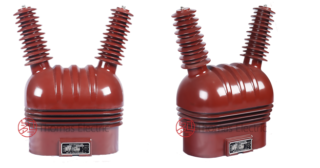
Product Shows
 Thomas Electric")
Working Principle
Operating on Faraday’s law of electromagnetic induction, the voltage transformer features a laminated magnetic core with primary winding connected to the system voltage and secondary winding providing proportional voltage output. The transformer operates on the voltage transformation principle, delivering standardized secondary voltage through connected burden while maintaining accurate phase relationships.
System Application Position
- Medium Voltage Distribution: 35kV outdoor substations and distribution systems
- Energy Metering: Revenue-grade electricity measurement systems
- Protection Circuits: Overvoltage, undervoltage, and distance protection schemes
- SCADA Integration: Supervisory control and data acquisition systems
Structural Overview
Epoxy resin cast construction with fully-enclosed design ensures superior insulation performance, moisture resistance, UV resistance, and mechanical strength. The pillar-type (post-type) outdoor mounting configuration provides excellent pollution performance and weather resistance while maintaining required electrical clearance and creepage distances for outdoor service environments.
Model Designation
 Thomas Electric")
Model Code Explanation
- J — Voltage transformer (VT / PT)
- D — Single-phase design
- Z — Support (pillar / post) type
- W — Outdoor installation
- 35 — Voltage class (kV)
- F — Fuse-equipped variant (JDZFW-35 models)
- X — Auxiliary secondary winding for open-delta connection (JDZXW-35 models)
Variant Differences
JDZW-35, JDZFW-35, JDZXW-35, and JDZXFW-35 represent different winding configurations:
- JDZW-35: Single secondary winding for metering or protection
- JDZFW-35: Dual secondary windings (two independent cores) for separate metering and protection functions, fuse-equipped
- JDZXW-35: Primary winding plus dual secondaries including auxiliary winding for open-delta residual voltage detection
- JDZXFW-35: Comprehensive configuration with dual secondaries plus auxiliary winding and fuse protection
Service Conditions
The JDZW-35 series voltage transformers are designed for outdoor operation under normal service conditions in medium-voltage power systems.
- Installation environment: Outdoor installation
- Altitude: Not exceeding 1000 m above sea level (higher altitude shall be specified for engineering confirmation)
- Ambient temperature: −5 °C to +40 °C
- Relative humidity: Daily average ≤ 95%, monthly average ≤ 90% (at +20 °C reference)
- Environmental conditions: Free from corrosive gases or vapors; free from explosive or flammable media; pollution severity level II per IEC 60815
Construction
Construction Design
- Structure: Pillar (post) type for outdoor mounting
- Insulation: Fully enclosed epoxy resin cast insulation with UV-resistant, anti-tracking formulation
- Core: Cold-rolled grain-oriented silicon steel laminations, heat-treated for optimized magnetic properties
- Casting technology: Advanced vacuum casting process eliminating voids and ensuring uniform insulation
- Terminal enclosure: Metal terminal box with sealed cover and provision for padlock security
The epoxy resin casting provides stable insulation properties and resistance to moisture, UV radiation, pollution, contamination, and aging for long-term outdoor service. The compact, fully-enclosed design eliminates internal moisture accumulation and requires minimal maintenance.
Windings & Terminal Marking
 Thomas Electric")
- Primary terminals: A, N (phase and neutral)
- Secondary terminals (Winding 1): 1a, 1n
- Secondary terminals (Winding 2): 2a, 2n (JDZFW-35, JDZXW-35, JDZXFW-35)
- Auxiliary winding terminals: da, dn (JDZXW-35, JDZXFW-35 for residual voltage detection)
Terminal markings follow standard VT polarity conventions. Under normal operating conditions, terminals marked ‘a’ are in phase with terminal ‘A’. Correct terminal identification shall be observed to ensure metering and protection performance. All secondary terminals are housed in the enclosed terminal box with multiple cable entry provisions.
Technical Data
This section provides selection-oriented technical data for the JDZW-35 series outdoor, cast-resin voltage transformer used in 35 kV class AC systems (50 Hz). Data shown below is intended for preliminary selection of accuracy class combinations, rated burdens, and voltage ratios.
Definitions: Accuracy class combination indicates available metering/protection cores in one VT (multi-core configuration may apply). Rated output (VA) is specified per secondary core. Insulation level specified as Um/LIPL/ACSD per IEC 61869-1.
Notation: All ratings are per nameplate values and factory test report. For configurations not listed, consult factory technical department for engineering support and custom specifications.
Data Reference
| Model | Voltage Ratio (V) |
Accuracy Class Combination |
Rated Output (VA) |
Maximum Output (VA) |
Insulation Level (kV) |
|---|---|---|---|---|---|
| JDZW-35 | 35000/100 | 0.2 | 75 | 1000 | 40.5/95/200 |
| JDZW-35 | 35000/100 | 0.5 | 100 | 1000 | 40.5/95/200 |
| JDZFW-35 | 35000/100/100 | 0.2/0.2 | 30/30 | 2 × 500 | 40.5/95/200 |
| JDZFW-35 | 35000/100/100 | 0.2/0.5 | 30/60 | 2 × 500 | 40.5/95/200 |
| JDZFW-35 | 35000/100/100 | 0.5/0.5 | 60/60 | 2 × 500 | 40.5/95/200 |
| JDZXW-35 | 35000/√3 / 100/√3 / 100/3 | 0.2/6P | 40/100 | 1000 | 40.5/95/200 |
| JDZXW-35 | 35000/√3 / 100/√3 / 100/3 | 0.5/6P | 80/100 | 1000 | 40.5/95/200 |
| JDZXW-35 | 35000/√3 / 100/√3 / 100/3 | 0.2/0.2/6P | 20/20/100 | 1000 | 40.5/95/200 |
| JDZXFW-35 | 35000/√3 / 100/√3 / 100/3 / 100/3 | 0.2/0.5/6P | 25/25/100 | 2 × 400 | 40.5/95/200 |
| JDZXFW-35 | 35000/√3 / 100/√3 / 100/3 / 100/3 | 0.5/0.5/6P | 40/40/100 | 2 × 400 | 40.5/95/200 |
Standards & Normative References
| Standard | Title | Application |
|---|---|---|
| IEC 61869-1 | Instrument Transformers – Part 1: General Requirements | General requirements |
| IEC 61869-3 | Instrument Transformers – Part 3: Additional Requirements for Voltage Transformers | VT-specific requirements |
| GB/T 20840.1 | Instrument Transformers – Part 1: General Requirements | National standard (aligned with IEC 61869 framework) |
| GB/T 20840.3 | Instrument Transformers – Part 3: Voltage Transformers | National VT requirements (aligned with IEC 61869-3) |
| IEC 60815 | Selection and Dimensioning of High-Voltage Insulators for Polluted Conditions | Outdoor insulation design and pollution severity classification |
| IEEE C57.13 | Standard Requirements for Instrument Transformers | Optional (North America project reference) |
| IEC 60068-2-17 | Environmental Testing – Salt Mist | Optional (project-specific environmental validation) |
| IEC 60085 | Electrical Insulation – Thermal Evaluation | Optional (insulation thermal evaluation reference) |
Factory Test Compliance
- Routine tests per applicable IEC/GB requirements (including polarity/marking, ratio verification, and accuracy verification per specified class and burden)
- Dielectric tests per insulation coordination requirements and applicable standard (power-frequency withstand test and lightning impulse test)
- Partial discharge test where specified by the project requirement
- Visual and dimensional inspection including marking and workmanship conformity
- Type and special tests as required by the project specification
Installation & Dimensions
- Outline dimensions and mounting details are provided in the dimensional drawings.
- The transformer shall be securely mounted on a stable concrete foundation or steel structure using the designated fixing holes.
- Primary connection is typically via overhead line conductor or busbar, depending on substation configuration.
- Adequate clearance shall be maintained for insulation coordination, heat dissipation, and maintenance access.
- For locations subject to seismic activity, additional mechanical reinforcement may be required per local standards.
Outlines
 Thomas Electric")
Connection Diagrams
 Thomas Electric")
Safety Notes
- Secondary circuit shall not be left open during operation as this may cause core saturation and overvoltage conditions.
- During inspection or maintenance, all secondary circuits shall be short-circuited and grounded before disconnecting any instruments.
- One point of each secondary circuit should be reliably grounded in accordance with applicable standards.
- All installation and maintenance work shall comply with local electrical safety regulations and utility requirements.
- For fused variants (JDZFW-35, JDZXFW-35), verify fuse ratings match the specified values and provide adequate discrimination with downstream protection.
Ordering Information
When placing an order, the required configuration shall be specified according to the local grid requirements, applicable standards, and project technical specification. The following parameters shall be clearly stated for technical confirmation and production release:
- Model variant (JDZW-35, JDZFW-35, JDZXW-35, or JDZXFW-35)
- Voltage ratio (primary voltage / secondary voltage(s))
- Application and accuracy requirements (metering and/or protection accuracy class combination)
- Rated burden (VA) for each secondary core/winding
- Insulation level (if different from standard 40.5/95/200 kV)
- Environmental conditions (altitude, pollution severity, special climatic requirements)
Selection Guidance
1: Determine required voltage ratio based on system voltage and secondary instrument requirements (typically 100V or 100/√3 V).
2: Select metering and/or protection accuracy requirements (e.g., 0.2 for revenue metering; 0.5 for indication; 6P for protection).
3: Confirm rated burden (VA) for each secondary circuit based on connected meters/relays and wiring losses.
4: Verify insulation level meets or exceeds system requirements based on network configuration and grounding method.
5: For open-delta residual voltage detection (ground fault indication), specify JDZXW-35 or JDZXFW-35 variants with auxiliary winding.
If local utility or project requirements apply (e.g., specific terminal arrangement, mounting height constraints, documentation language, enhanced pollution performance, or required certificates), specify them at the ordering stage. Special configurations shall be confirmed by technical agreement and final data sheet prior to production.