Product Overview
Functional Definition
The JDZW-35R and JDZFW-35W2 series voltage transformers (PT) are precision electromagnetic instruments designed for accurate voltage measurement, energy metering, and relay protection applications in 35kV outdoor medium-voltage AC power systems. These transformers utilize electromagnetic induction principles to provide galvanically isolated secondary voltage signals proportional to primary voltage.
Key Ratings
| Item | Specification (per order / nameplate) |
|---|---|
| System voltage class | 35 kV class (outdoor distribution and substation applications) |
| Rated frequency | 50 Hz or 60 Hz (specify at order) |
| Rated primary voltage | 35 kV / √3 (line-to-ground) |
| Rated secondary voltage | 100 V / √3 (standard); dual secondary available on JDZFW-35W2 |
| Accuracy classes | 0.2 class / 0.5 class (metering and protection cores as specified) |
| Rated burden | 30 VA, 50 VA, 80 VA per winding as specified |
| Limit output capacity | 800 VA (JDZFW-35W2) / 1000 VA (JDZW-35W2) |
| Burden power factor | cosφ = 0.8 (lagging) unless otherwise specified |
| Rated voltage factor | 1.2 Un continuous / 1.9 Un for 30 seconds (per IEC 61869-3) |
| Insulation level | Um / Ud / Uac: 40.5 / 95 / 200 kV (power frequency wet / lightning impulse / switching impulse) |
| Applicable standards | IEC 61869-1 / IEC 61869-3; GB/T 20840.1 / 20840.3; JB/T 5277 |
| Variants | JDZW-35R (single secondary) / JDZFW-35W2 (dual secondary) |
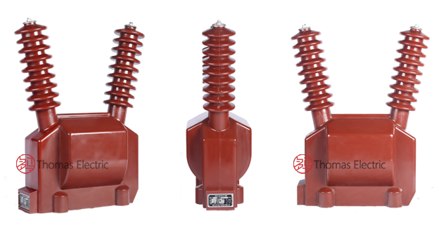
Product Shows

Working Principle
Operating on Faraday’s law of electromagnetic induction, the voltage transformer features a laminated iron core with primary winding connected to the high-voltage system and secondary windings providing standardized low-voltage output. The magnetic flux linking both windings induces proportional voltage in the secondary, delivering galvanically isolated measurement signals to connected metering and protection devices.
System Application Position
- Outdoor Substations: 35kV switchyards and distribution substations
- Energy Metering: Revenue-grade electricity measurement systems
- Protection Circuits: Overvoltage, undervoltage, and distance protection schemes
- Monitoring Systems: SCADA and grid automation voltage monitoring
Structural Overview
Epoxy resin cast construction with fully-enclosed pillar-type design ensures superior insulation performance, UV resistance, moisture resistance, and mechanical strength. The outdoor-rated design provides reliable operation in harsh environmental conditions while maintaining excellent electrical clearance and creepage distances. Unlike oil-filled designs, the solid epoxy casting eliminates fire hazards and requires minimal maintenance throughout its service life.
Model Designation

Code Explanation
- J — Voltage transformer (VT)
- D — Single-phase
- Z — Pillar (post) type mounting
- W — Outdoor installation design
- 35 — Voltage class (kV)
- R — Epoxy resin casting (fully enclosed insulation)
- W2 — Winding configuration code (dual secondary on JDZFW variant)
Variant Differences
JDZW-35R provides a single secondary winding for unified metering or protection applications. JDZFW-35W2 provides dual independent secondary windings, allowing simultaneous connection of metering and protection circuits with galvanic isolation between secondary functions. Both variants share identical primary voltage rating and insulation levels; selection depends on the project’s metering and protection circuit architecture.
Service Conditions
The JDZW-35R and JDZFW-35W2 series voltage transformers are designed for outdoor operation under normal service conditions in 35kV medium-voltage power systems.
- Installation: Outdoor installation (IP-rated enclosure)
- Altitude: ≤ 1000 m (higher altitude requires derating or enhanced insulation specification)
- Ambient temperature: −25 °C to +40 °C
- Relative humidity: Daily average ≤ 95%, monthly average ≤ 90% (condensation permissible)
- Pollution level: Class II or higher per IEC 60815 (Class III/IV available for heavy pollution environments)
- Environmental conditions: UV exposure resistance; suitable for industrial, coastal, or high-pollution areas; no severe mechanical shock or vibration
Construction
Construction Design
- Structure: Pillar (post) type for outdoor substation and switchyard mounting
- Insulation: Fully enclosed epoxy resin cast insulation system
- Core: Laminated silicon steel core design for low losses and high linearity
- Windings: Primary and secondary windings with class H thermal rating
- Terminals: Weatherproof junction box with anti-theft provisions
- Base: Steel channel mounting base with four-hole fixing pattern supporting any installation orientation
The epoxy resin casting provides stable insulation properties and exceptional resistance to moisture, contamination, UV radiation, arc tracking, and aging for long-term outdoor service. The solid dielectric eliminates oil leakage, fire hazards, and routine oil maintenance requirements.
Windings & Terminal Marking

- Primary terminals: 1U / 1X (high-voltage side)
- Secondary terminals (JDZW-35R): 1u / 1x (single winding)
- Secondary terminals (JDZFW-35W2, Group 1): 1u / 1x (metering winding)
- Secondary terminals (JDZFW-35W2, Group 2): 2u / 2x (protection winding)

Terminal markings follow standard VT polarity conventions per IEC 61869-3. Under normal operating conditions with balanced three-phase voltage, terminal 1U is at higher potential relative to 1X, and secondary terminals 1u and 2u are correspondingly at higher potential. Correct terminal identification shall be observed to ensure metering accuracy and protection directionality.
Technical Parameters
| Type | Rated Voltage Ratio (kV) |
Accuracy Class |
Rated Secondary Load (VA) |
Limit Output (VA) |
Rated Insulation Level (kV) |
|---|---|---|---|---|---|
| JDZW-35W2 | 35/0.1 | 0.2 | 30 | 1000 | 40.5/95/200 |
| 0.5 | 80 | ||||
| JDZFW-35W2 | 35/0.1/0.1 | 0.2 / 0.5 | 30/30 or 30/50 | 800 | 40.5/95/200 |
| 0.5 / 0.5 | 50/50 |
Accuracy and Burden
The voltage transformer’s accuracy is guaranteed when operating at rated frequency, rated primary voltage, and with burden (in VA and power factor) not exceeding the rated burden specified for each accuracy class. Voltage error and phase displacement shall comply with the limits defined in IEC 61869-3 and GB/T 20840.3 for the specified accuracy class.
| Accuracy Class |
Voltage Error (max) |
Phase Displacement (max) |
Typical Application |
|---|---|---|---|
| 0.2 | ±0.2% | ±10 minutes | Precision metering, revenue measurement |
| 0.5 | ±0.5% | ±20 minutes | General metering, monitoring, protection |
Insulation Levels
| Test Type | Voltage Level |
|---|---|
| Highest voltage for equipment (Um) | 40.5 kV |
| Power-frequency withstand voltage (wet, 1 min) | 95 kV |
| Lightning impulse withstand voltage (1.2/50 μs) | 200 kV (peak) |
| Secondary winding power-frequency withstand | 3 kV (1 min) |
| Inter-winding withstand (dual secondary) | 3 kV (1 min) |
Standards Compliance
The JDZW-35R and JDZFW-35W2 voltage transformers are designed, manufactured, and tested in full compliance with the following national and international standards:
Applicable Standards
- IEC 61869-1: Instrument transformers – Part 1: General requirements
- IEC 61869-3: Instrument transformers – Part 3: Additional requirements for inductive voltage transformers
- GB/T 20840.1: Instrument transformers – Part 1: General requirements
- GB/T 20840.3: Instrument transformers – Part 3: Additional requirements for inductive voltage transformers
- JB/T 5277: General specification for voltage transformers
- IEC 60815: Selection and dimensioning of high-voltage insulators (pollution performance)
Type and Routine Tests
Each transformer undergoes comprehensive factory testing to verify compliance with applicable standards:
- Ratio and polarity verification at rated voltage and frequency
- Voltage error and phase displacement test at specified accuracy class and burden combinations
- Power-frequency withstand voltage test (primary-to-ground, secondary-to-ground, inter-winding)
- Lightning impulse withstand test where specified by project requirements
- Temperature rise test at rated burden and continuous voltage factor
- Partial discharge test where specified (< 10 pC at Um / √3)
- Visual and dimensional inspection including marking and workmanship conformity
- Type and special tests as required by the project specification
Installation & Dimensions
Outlines

- Outline dimensions and mounting details are provided in the dimensional drawings.
- The transformer shall be securely mounted using the four-hole steel channel base; installation orientation is flexible (any direction).
- Primary connection is made via bolted terminal 1U; ensure adequate creepage and clearance to grounded surfaces.
- Secondary terminals are housed in a weatherproof junction box with cable entry provisions.
- Adequate clearance shall be maintained for insulation coordination, heat dissipation, and maintenance access.
- Grounding connection must be provided per local electrical safety codes.
Safety Notes
- Primary side shall be de-energized and grounded before performing any maintenance work on the voltage transformer.
- Secondary fusing or circuit protection shall be installed per project protection coordination study.
- One point of the secondary circuit should be reliably grounded in accordance with applicable standards to prevent dangerous voltages in case of insulation failure.
- Do not exceed rated voltage factor limits (1.2 Un continuous, 1.9 Un for 30 seconds) to avoid core saturation and thermal damage.
- All installation and maintenance work shall comply with local electrical safety regulations and utility practices.
Ordering Information
When placing an order, the required configuration shall be specified according to the local grid requirements, applicable standards, and project technical specification. The following parameters shall be clearly stated for technical confirmation and production release:
- Model designation: JDZW-35W2 (single secondary) or JDZFW-35W2 (dual secondary)
- Rated voltage ratio: 35 / 0.1 kV or 35 / 0.1 / 0.1 kV
- Accuracy class requirements: 0.2 and/or 0.5 class (specify per winding)
- Rated burden: 30 VA, 50 VA, or 80 VA per secondary winding
- Insulation level: Standard 40.5/95/200 kV or enhanced specification
- Pollution class: Class II (standard) or Class III/IV for heavy pollution environments
- Altitude: Standard (≤1000 m) or high-altitude specification
If local utility or project requirements apply (e.g., residual voltage winding for earth-fault detection, specific terminal arrangements, mounting constraints, documentation language, or required certificates), specify them at the ordering stage. Special configurations shall be confirmed by technical agreement and final data sheet prior to production.