Product Overview
Functional Definition
The JDZW-20 and JDZW2-20 series voltage transformers are precision electromagnetic instruments designed for accurate voltage measurement, energy metering, and relay protection applications in medium-voltage AC power systems. These transformers utilize electromagnetic induction principles to provide galvanically isolated secondary voltage signals proportional to primary voltage. The outdoor epoxy resin cast construction ensures reliable performance in variable climatic conditions.
Key Ratings
| Item | Specification (per order / nameplate) |
|---|---|
| System voltage class | 20 kV class (outdoor substation and distribution applications) |
| Rated frequency | 50 Hz or 60 Hz |
| Rated voltage ratio | 20000/√3 V / 100/√3 V or 20000/√3 V / 100/√3 V / 100/3 V |
| Secondary voltage (standard) | 100 V or 100/√3 V (line-to-ground) |
| Accuracy classes | 0.2 and/or 0.5 (metering cores as specified) |
| Rated output | Per core/winding as specified (VA): 25 VA (0.2 class) / 50 VA (0.5 class) |
| Maximum output | 600 VA (continuous) |
| Insulation level | 50 kV (rated insulation level per applicable standard) |
| Operating temperature | −25 °C to +40 °C (outdoor installation) |
| Installation environment | Outdoor (epoxy resin weatherproof construction) |
| Applicable standards | IEC 186; GB 1207-2006 |
| Model variants | JDZW-20 (single secondary) / JDZW2-20 (dual secondary with residual voltage output) |
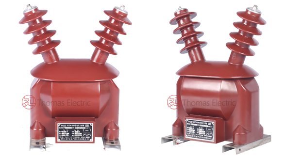
Product Shows

Working Principle
Operating on Faraday’s law of electromagnetic induction, the voltage transformer features a laminated magnetic core with primary winding connected to the system voltage and secondary windings wound around the core. The alternating primary voltage induces proportional voltage in the secondary winding, delivering standardized output voltage through connected burden. The epoxy resin insulation system ensures reliable isolation between primary and secondary circuits in outdoor environments.
System Application Position
- Medium Voltage Distribution: 20 kV outdoor substations and distribution networks
- Energy Metering: Revenue-grade voltage measurement for billing systems
- Voltage Monitoring: Real-time voltage level supervision and regulation
- Protection Circuits: Overvoltage, undervoltage, and earth fault protection schemes
- Ungrounded/Weak-grounded Systems: Residual voltage detection for ground fault indication (JDZW2-20 variant)
Structural Overview
Epoxy resin cast construction with fully-enclosed outdoor design ensures superior insulation performance, UV resistance, moisture resistance, and mechanical strength. The weather-resistant enclosure provides reliable operation across diverse climatic conditions while maintaining excellent electrical clearance and creepage distances. The outdoor post-type configuration enables direct installation in open-air substations without additional protective enclosures.
Model Designation

Model Code Explanation
- J — Voltage transformer (VT)
- D — Single-phase
- Z — Cast-resin (epoxy) insulated structure
- W — Outdoor application (weather-resistant)
- 20 — Voltage class (kV)
- 2 (in JDZW2) — Dual secondary windings with residual voltage output for ground fault detection
Variant Differences
- JDZW-20: Single secondary winding configuration for voltage measurement and metering applications
- JDZW2-20: Dual secondary winding configuration with additional residual voltage output (open delta connection) for ground fault detection in ungrounded or weak-grounded systems
Both variants are electrically compatible with 20 kV systems and share the same insulation level, outdoor construction, and mounting requirements. Selection depends on the system grounding configuration and protection scheme requirements.
Service Conditions
The JDZW-20/JDZW2-20 series voltage transformers are designed for outdoor operation under normal service conditions in medium-voltage power systems.
- Installation environment: Outdoor installation (weather-resistant epoxy resin construction)
- Altitude: Not exceeding 1000 m above sea level (higher altitude shall be specified for engineering confirmation)
- Ambient temperature: −25 °C to +40 °C
- Daily average temperature: Not exceeding +30 °C
- Relative humidity: Up to 85% (outdoor environment)
- Environmental conditions: Free from severe industrial pollution or corrosive gases that may affect insulation performance; no explosive or flammable media; designed to withstand outdoor climatic conditions including rain, snow, and UV exposure
Construction
Construction Design
- Structure: Outdoor post-type for substation and distribution applications
- Insulation: Fully enclosed epoxy resin cast insulation with UV-resistant properties
- Core: Laminated magnetic core design optimized for voltage transformation
- System: Integrated primary and secondary insulation system suitable for outdoor exposure
- Enclosure: Weather-resistant epoxy resin housing providing IP-rated protection
The epoxy resin casting provides stable insulation properties and resistance to moisture, UV radiation, contamination, and aging for long-term outdoor service. The fully-enclosed design eliminates the need for additional protective enclosures.
Windings & Terminal Marking

- Primary terminals: A / X (high voltage side)
- Secondary terminals (measurement winding): a / x or a / x / xₐ (depending on configuration)
- Residual voltage terminals (JDZW2-20 only): Open delta connection terminals for ground fault detection
Terminal markings follow standard VT polarity conventions per IEC and GB standards. Correct terminal identification shall be observed to ensure metering and protection performance. Fused primary connections are recommended for overcurrent protection of the VT primary winding.
Technical Data
This section provides selection-oriented technical data for the JDZW-20 / JDZW2-20 series outdoor, epoxy resin voltage transformer used in 20 kV class AC systems (50 Hz / 60 Hz). Data shown below is intended for preliminary selection of voltage ratio, accuracy class combinations, and rated output capacity.
Definitions: Rated voltage ratio indicates the primary-to-secondary voltage transformation ratio. Rated output (VA) is specified per secondary core and represents the maximum burden the VT can supply while maintaining accuracy. Maximum output (VA) represents the thermal limit for continuous operation. Rated insulation level is the withstand voltage for dielectric testing.
Notation: Voltage ratios are expressed as line-to-ground values for system application. Acceptance shall be based on nameplate values and the factory test report.
Data Reference
| Model | Rated Voltage Ratio (V) |
Rated Output 0.2 Class (VA) |
Rated Output 0.5 Class (VA) |
Maximum Output (VA) |
Rated Insulation Level (kV) |
|---|---|---|---|---|---|
| JDZW-20 | 20000/√3 / 100/√3 | 25 | 50 | 600 | 50 |
| JDZW2-20 | 20000/√3 / 100/√3 / 100/3 | 25 | 50 | 600 | 50 |
Standards & Normative References
| Standard | Title | Application |
|---|---|---|
| IEC 186 | Voltage Transformers | International VT requirements and test methods |
| GB 1207-2006 | Voltage Transformers | National standard for VT design, testing, and performance |
| IEC 60044-2 | Instrument Transformers – Part 2: Inductive Voltage Transformers | General VT requirements (reference standard) |
| GB/T 22071.1 | Instrument Transformers – Part 1: General Requirements | General requirements for instrument transformers |
| IEC 60529 | Degrees of Protection Provided by Enclosures (IP Code) | Environmental protection rating verification |
| IEC 60085 | Electrical Insulation – Thermal Evaluation | Insulation thermal class evaluation reference |
Factory Testing Compliance
- Routine tests per GB 1207-2006 requirements (including polarity/marking verification, ratio verification, and accuracy verification per specified class and burden)
- Dielectric tests including power frequency withstand voltage test and impulse voltage test per insulation coordination requirements
- Partial discharge test per GB 1207-2006 requirements to verify insulation quality
- Temperature rise test at maximum rated output to verify thermal performance
- Visual and dimensional inspection including marking and workmanship conformity
- Type and special tests as required by the project specification
Installation & Dimensions

- Outline dimensions and mounting details are provided in the dimensional drawings (consult factory for specific variant dimensions)
- The transformer shall be securely mounted using the designated fixing holes on the mounting base
- Primary connection shall be made via insulated bushing terminals with appropriate clearances maintained
- Adequate clearance shall be maintained for insulation, heat dissipation, and maintenance access per local electrical codes
- Outdoor installation requires consideration of wind loading, ice loading (where applicable), and seismic conditions per site requirements
Connection Diagrams

Y-Connection (Wye Connection):
Used for three-phase voltage measurement in star-connected systems. Three single-phase JDZW-20 units are connected with their primary windings in star configuration, with the neutral point grounded or isolated depending on system grounding practice.
V-Connection (Open Delta):
Used for three-phase voltage measurement in fully-insulated systems. Two single-phase JDZW-20 units are connected in open delta configuration to provide three-phase voltage measurement with reduced hardware cost. Suitable for systems where full three-phase voltage monitoring is not critical.
Ground Fault Detection (JDZW2-20):
Three JDZW2-20 units connected in broken delta (open delta) configuration on the residual voltage winding. The open delta output provides zero-sequence voltage signal for ground fault detection and indication in ungrounded or impedance-grounded systems.
Safety Notes
- Primary voltage connections must be performed only when the circuit is de-energized and properly isolated
- Secondary circuit burden shall not exceed the rated output for the specified accuracy class
- One point of the secondary circuit should be reliably grounded in accordance with applicable standards
- Primary fuses are recommended for VT protection; consult factory for appropriate fuse rating selection
- Regular inspection and cleaning are recommended to maintain insulation performance; inspect for surface contamination, tracking, or physical damage
- All installation and maintenance work shall comply with local electrical safety regulations and utility standards
Ordering Information
When placing an order, the required configuration shall be specified according to the local grid requirements, applicable standards, and project technical specification. The following parameters shall be clearly stated for technical confirmation and production release:
- Model designation (JDZW-20 or JDZW2-20)
- Rated voltage ratio (20000/√3 V / 100/√3 V or equivalent)
- Accuracy class requirements (0.2 and/or 0.5 for metering applications)
- Rated output (VA) for each accuracy class
- System frequency (50 Hz or 60 Hz)
- Quantity (typically 3 units for three-phase application)
- Connection configuration (Y-connection, V-connection, or broken delta for ground fault detection)
How to Select:
1. Determine system voltage class (20 kV) and grounding configuration (grounded, ungrounded, or impedance-grounded).
2. Select model variant: JDZW-20 for standard voltage measurement; JDZW2-20 for ground fault detection capability.
3. Specify accuracy class (0.2 for revenue metering; 0.5 for general measurement and protection).
4. Confirm rated output (VA) based on connected meters, relays, and wiring losses; ensure total burden does not exceed rated output.
5. Specify connection configuration based on system requirements (Y, V, or broken delta).
If local utility or project requirements apply (e.g., special insulation level, mounting configuration, terminal arrangement, documentation language, or required certificates), specify them at the ordering stage. Special configurations shall be confirmed by technical agreement and final datasheet prior to production.