Product Overview
Functional Definition
The JDZXF9-35W and JDZX9-35 series outdoor cast-resin voltage transformer, are precision electromagnetic instruments designed for accurate voltage measurement, energy metering, and relay protection applications in 35 kV outdoor AC power systems. These transformers utilize electromagnetic induction principles to provide galvanically isolated secondary voltage signals proportional to primary voltage.
Key Ratings
| Item | Specification (per order / nameplate) |
|---|---|
| System voltage class | 35 kV class (outdoor distribution and transmission applications) |
| Rated frequency | 50 Hz (60 Hz available upon request) |
| Rated voltage ratio | 35000/√3/100/√3 or 35000/√3/100/√3/100/√3 (multi-winding configurations) |
| Accuracy classes | Metering and/or protection windings as specified (e.g., 0.2 / 0.5, 6P) |
| Rated burden | Per winding as specified (VA) |
| Burden power factor | cosφ = 0.8 (inductive) unless otherwise specified by the project standard |
| Insulation level | 40.5/95/200 kV (Um/LIPL/ACWV) |
| Pollution grade | Grade II (Grade IV available) |
| Applicable standards | IEC 61869-3; GB 20840.3-2013; GB 20840.1-2010; GB 1207-2006 |
| Structural variants | JDZX9-35 (single protection winding) / JDZXF9-35 (dual metering, single protection winding) |
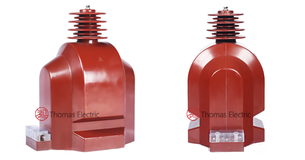
Product Show
 Thomas Electric")
Working Principle
Operating on Faraday’s law of electromagnetic induction, the voltage transformer features a laminated magnetic core with primary winding connected to the high-voltage line and secondary windings providing standardized low-voltage signals. The magnetic flux generated by primary voltage induces proportional voltage in the secondary winding, delivering standardized output voltage through connected burden.
System Application Position
- Medium Voltage Distribution: 35 kV outdoor switchgear and distribution systems
- Energy Metering: Revenue-grade electricity measurement and tariff systems
- Protection Circuits: Overvoltage, undervoltage, and directional protection schemes
- SCADA Integration: Supervisory control and data acquisition systems
Structural Overview
Epoxy resin cast construction with fully-enclosed outdoor design ensures superior insulation performance, UV resistance, moisture resistance, and mechanical strength. The support-type mounting configuration provides stable installation in outdoor substations while maintaining excellent electrical clearance and creepage distances for Grade II and Grade IV pollution environments.
Model Designation
 Thomas Electric")
Model Code Explanation
- J — Voltage transformer (VT / PT)
- D — Single-phase
- Z — Cast-resin (epoxy) insulated, fully enclosed structure
- X — Outdoor (weatherproof) design
- F — Multiple metering windings (JDZXF9 only)
- 9 — Design code (platform/iteration)
- 35 — Voltage class (kV)
- W — Outdoor pollution grade variant (extended creepage)
Variant Differences
JDZX9-35 features one metering winding and one protection winding, suitable for standard metering and protection applications. JDZXF9-35 features two separate metering windings plus one protection winding, enabling independent metering circuits for dual-custody or backup measurement systems. Both models are electrically equivalent when specified with identical voltage ratios, accuracy classes, burdens, and insulation levels.
Service Conditions
The JDZXF9-35W / JDZX9-35W series voltage transformers are designed for outdoor operation under normal service conditions in medium-voltage power systems.
- Installation environment: Outdoor installation
- Altitude: Not exceeding 1000 m above sea level (higher altitude shall be specified for engineering confirmation)
- Ambient temperature: −25 °C to +40 °C
- Daily average temperature: Not exceeding 30 °C
- Pollution grade: Grade II standard (Grade IV available for severe pollution environments)
- Environmental conditions: Suitable for outdoor atmospheric conditions; no severe corrosive gases or explosive media; resistant to UV radiation and moisture
Construction
Construction Design
- Structure: Support (post) type for outdoor substation mounting
- Insulation: Fully enclosed epoxy resin cast insulation with UV-resistant outer surface
- Core: Silicon steel laminated core design with low no-load loss
- System: Integrated primary and secondary insulation system with extended creepage for pollution resistance
The epoxy resin casting provides stable insulation properties and resistance to moisture, UV degradation, contamination, thermal cycling, and aging for long-term outdoor service in harsh environments.
Windings & Terminal Marking
 Thomas Electric")
- Primary terminals: A (line) / X (neutral or ground-side connection)
- Secondary terminals (Metering Winding 1): a1 / x1 / xa
- Secondary terminals (Metering Winding 2, JDZXF9 only): a2 / x2 / xa
- Secondary terminals (Protection Winding): ad / xd / xd
Terminal markings follow IEC 61869 and GB 1207 polarity conventions. Under normal operating conditions, when terminal A is at positive potential relative to X, terminals a1/a2/ad are simultaneously at positive potential relative to x1/x2/xd respectively. Correct terminal identification shall be observed to ensure metering and protection performance. At least one point of each secondary winding shall be grounded per safety requirements.
Technical Data
This section provides selection-oriented technical data for the JDZXF9-35 / JDZX9-35 series outdoor, cast-resin voltage transformer used in 35 kV class AC systems (50 Hz / 60 Hz). Data shown below is intended for preliminary selection of voltage ratio, accuracy class combinations, and rated burdens.
Definitions: Accuracy class combination indicates available metering/protection windings in one VT (multi-winding configuration applies). Rated output (VA) is specified per secondary winding. Um is the maximum system voltage. LIPL is lightning impulse protective level. ACWV is AC withstand voltage.
Notation: Voltage ratios expressed as phase-to-ground values (35000/√3 = 20207 V line-to-ground for 35 kV system). Acceptance shall be based on nameplate values and the factory test report.
Data Reference
| Model | Rated Voltage Ratio (V) |
Accuracy Class Combination |
Rated Output (VA) |
Maximum Output (VA) |
Rated Insulation Level (kV) |
|---|---|---|---|---|---|
| JDZX9-35 | 35000/√3 / 100/√3 / 100/3 | 0.2 / 6P | 30 / 100 | 600 | 40.5 / 95 / 200 |
| 0.5 / 6P | 50 / 100 | ||||
| JDZXF9-35 | 35000/√3 / 100/√3 / 100/√3 / 100/3 | 0.2 / 0.2 / 6P | 20 / 20 / 100 | 2×300 (metering) 600 (protection) |
|
| 0.2 / 0.5 / 6P | 25 / 30 / 100 | ||||
| 0.5 / 0.5 / 6P | 30 / 30 / 100 | ||||
| Custom combinations | As specified |
Note: Custom accuracy class and voltage ratio combinations available upon request. Only one voltage ratio shall be used at a time; simultaneous use of multiple taps is not permitted
Standards & Normative References
| Standard | Title | Application |
|---|---|---|
| IEC 61869-1 | Instrument Transformers – Part 1: General Requirements | General requirements |
| IEC 61869-3 | Instrument Transformers – Part 3: Additional Requirements for Voltage Transformers | VT-specific requirements |
| GB 20840.1-2010 | Instrument Transformers – Part 1: General Requirements | National standard (aligned with IEC 61869 framework) |
| GB 20840.3-2013 | Instrument Transformers – Part 3: Voltage Transformers | National VT requirements (aligned with IEC 61869-3) |
| GB 1207-2006 | Electromagnetic Voltage Transformers | National VT standard where specified by the project |
| IEC 60507 | Artificial Pollution Tests on High-Voltage Insulators | Pollution grade verification |
| IEC 60085 | Electrical Insulation – Thermal Evaluation | Insulation thermal class evaluation reference |
Factory Testing Compliance
- Routine tests per applicable IEC/GB requirements (including polarity/marking verification, voltage ratio verification, and accuracy verification per specified class and burden)
- Dielectric tests per insulation coordination requirements and applicable standard (ACWV, LIPL)
- Partial discharge test where specified by the project requirement
- Visual and dimensional inspection including marking, workmanship conformity, and creepage distance verification
- Type and special tests as required by the project specification (temperature rise, pollution test, seismic qualification)
Installation & Dimensions
Outline
 Thomas Electric")
Wiring Principles
 Thomas Electric")
- Outline dimensions and mounting details are provided in the dimensional drawings.
- The transformer shall be securely mounted using the designated fixing holes on stable outdoor foundation or structure.
- Primary terminal connection shall be made via overhead line terminal or busbar connector.
- Adequate clearance shall be maintained for insulation, heat dissipation, lightning protection, and maintenance access.
- All secondary circuits shall be properly grounded at one point per winding group.
- Installation shall comply with local electrical code and utility requirements for outdoor substations.
Safety Notes
- Primary circuit disconnection required before any inspection or maintenance work.
- During inspection or maintenance, all primary terminals shall be visibly disconnected and grounded.
- At least one point of each secondary winding group shall be reliably grounded per IEC 61869-1 and local code.
- All installation and maintenance work shall comply with local electrical safety regulations and utility procedures.
- Observe minimum clearance requirements for live-work exclusion zones per applicable voltage class.
Ordering Information
When placing an order, the required configuration shall be specified according to the local grid requirements, applicable standards, and project technical specification. The following parameters shall be clearly stated for technical confirmation and production release:
- Rated voltage ratio (primary/secondary)
- Application and accuracy requirements (metering and/or protection accuracy class combination)
- Rated burden (VA) for each secondary winding
- Insulation level requirements: Um / LIPL / ACWV
- Pollution grade: Standard Grade II or extended Grade IV creepage
- Frequency: 50 Hz or 60 Hz
- Special requirements: Altitude correction, seismic qualification, terminal arrangement, test requirements
If local utility or project requirements apply (e.g., specific test certificates, terminal arrangement, mounting constraints, documentation language, altitude correction factors, or seismic qualification), specify them at the ordering stage. Special configurations shall be confirmed by technical agreement and final data sheet prior to production.