Product Overview
The JLS-20KV outdoor oil-immersed combined instrument transformer, is a precision electromagnetic metering and measurement solution designed for high-voltage AC power systems. This integrated unit comprises two single-phase fully-insulated voltage transformers (VT) configured in three-phase V/V connection and two current transformers (CT) series-connected in A-phase and C-phase, providing simultaneous current and voltage transformation for outdoor substation applications.
Key Ratings
| Item | Specification (per order / nameplate) |
|---|---|
| System voltage class | 20 kV / 22 kV class (outdoor distribution and substation applications) |
| Rated frequency | 50 Hz / 60 Hz |
| Rated secondary current (CT) | 1 A or 5 A |
| Rated secondary voltage (VT) | 100 V / 100/√3 V (line-to-ground) in V/V configuration |
| Accuracy classes (CT) | 0.2, 0.2S, 0.5 for metering applications as specified |
| Accuracy classes (VT) | 0.2, 0.5 for metering applications as specified |
| Connection configuration | Two VT units in V/V connection; two CT units in A-phase and C-phase |
| Insulation structure | Oil-immersed, fully-insulated design |
| Moisture protection | Anti-moisture device integrated on tank cover |
| Applicable standards | GB 17201-2006 (metering box); GB/T 20840.1-2010, GB/T 20840.2-2014 (CT); GB/T 20840.1-2010, GB/T 20840.3-2013 (VT) |
| Installation environment | Outdoor substation, distribution, and metering applications |
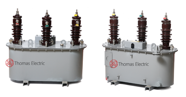
Product Shows

Working Principle
The JLS-20 combined transformer operates on electromagnetic induction principles. The voltage transformer section converts high-voltage signals to standardized low-voltage output through magnetic coupling, while the current transformer section provides galvanically isolated current signals proportional to primary current. The V/V connection configuration enables three-phase voltage measurement using two single-phase VT units, providing economical and space-efficient voltage transformation for outdoor metering installations.
System Application Position
- Outdoor Distribution Systems: 20 kV / 22 kV outdoor substations and distribution networks
- Energy Metering: Revenue-grade electricity measurement with active and reactive energy meters
- Rural Electrification: Outdoor substations in rural and agricultural power supply systems
- Industrial Installations: Small-scale industrial substations and power transformation facilities
- Urban Distribution: Compact outdoor metering cabinets in urban distribution networks
Structural Overview
Oil-immersed construction with fully-enclosed square tank design ensures superior insulation performance, environmental protection, and long service life. The integrated mounting configuration combines VT and CT functions in a single compact unit, reducing footprint and installation complexity in outdoor environments. The moisture-resistant tank cover prevents moisture ingress, extending equipment service life and enhancing resistance to harsh outdoor conditions.
Model Designation

Model Code Explanation
- J — Metering box / Combined transformer assembly
- L — Current transformer (CT) component
- S — Outdoor (Shi Wai) installation type
- 20 — Voltage class (20 kV nominal, also applicable to 22 kV systems)
- KV — Voltage unit designation
Configuration Details
The JLS-20KV and JLS-22KV models are functionally identical, with voltage class designation adapted to regional grid standards (20 kV or 22 kV nominal system voltage). The combined transformer integrates two single-phase voltage transformers in V/V configuration and two current transformers in series connection (A-phase and C-phase), providing comprehensive three-phase metering capability in a single outdoor-rated enclosure.
Service Conditions
The JLS-20KV series combined transformers are designed for outdoor operation under specified environmental conditions in medium-voltage power distribution systems.
- Installation environment: Outdoor installation in substations and distribution facilities
- Altitude: ≤ 2000 m above sea level (higher altitude shall be specified for engineering confirmation)
- Ambient temperature: −40 °C to +40 °C
- Relative humidity: Monthly average ≤ 90%
- System frequency: 50 Hz / 60 Hz AC systems
- Environmental conditions: Free from corrosive gases, flammable media, and severe pollution; no excessive vibration or mechanical shock
- Lightning protection: Zinc oxide surge arrester required within 1 meter of installation for lightning protection
Construction
Construction Design
- Structure: Outdoor oil-immersed combined configuration
- Tank design: Square sealed oil tank with lifting ring on top cover
- Insulation medium: Transformer oil immersion for VT and CT components
- VT configuration: Two single-phase fully-insulated voltage transformers in V/V connection
- CT configuration: Two electromagnetic current transformers series-connected in A-phase and C-phase
- Moisture protection: Anti-moisture device on tank cover with breathing mechanism
- Monitoring features: Oil level indicator, grounding terminal, and oil drain valve
- Mounting: Fixed installation on pole plate within oil tank assembly
The oil-immersed design provides stable insulation properties and thermal management for long-term outdoor service. The integrated moisture barrier extends service life by preventing moisture ingress into the oil, which is a common degradation mechanism in outdoor transformer installations.
Windings & Terminal Marking

Current Transformer Terminals:
- Primary terminals (A-phase CT): P1A / P2A
- Secondary terminals (A-phase CT): S1A / S2A
- Primary terminals (C-phase CT): P1C / P2C
- Secondary terminals (C-phase CT): S1C / S2C
Voltage Transformer Terminals:
- Primary terminals (VT Unit 1): A / X (line-to-ground)
- Secondary terminals (VT Unit 1): a / x (100 V output)
- Primary terminals (VT Unit 2): B / X (line-to-ground, shared neutral)
- Secondary terminals (VT Unit 2): b / x (100 V output)
Terminal markings follow standard instrument transformer polarity conventions. Correct terminal identification shall be observed to ensure proper three-phase metering performance in V/V configuration and accurate energy measurement.
Technical Data
This section provides selection-oriented technical data for the JLS-20KV outdoor oil-immersed combined instrument transformer used in 20 kV / 22 kV class AC systems (50 Hz / 60 Hz). Data shown below is intended for preliminary selection of transformation ratios, accuracy classes, rated burdens, and environmental specifications.
Definitions: Transformation ratio (CT) indicates primary to secondary current ratio (e.g., 50/5 A, 100/5 A). Transformation ratio (VT) indicates primary to secondary voltage ratio (e.g., 20000/100 V). Accuracy class defines measurement precision for metering applications. Rated burden (VA) is specified per secondary output. Moisture protection indicates anti-moisture device status.
Notation: Specifications may vary based on customer requirements and regional grid standards. Acceptance shall be based on nameplate values and factory test report.
Standards & Normative References
| Standard | Title | Application |
|---|---|---|
| GB 17201-2006 | Metering Box for Electricity Metering | Combined metering box requirements |
| GB/T 20840.1-2010 | Instrument Transformers – Part 1: General Requirements | General requirements for CT and VT |
| GB/T 20840.2-2014 | Instrument Transformers – Part 2: Current Transformers | CT-specific requirements |
| GB/T 20840.3-2013 | Instrument Transformers – Part 3: Voltage Transformers | VT-specific requirements |
| IEC 61869-1 | Instrument Transformers – Part 1: General Requirements | International general requirements (reference) |
| IEC 61869-2 | Instrument Transformers – Part 2: Additional Requirements for Current Transformers | International CT requirements (reference) |
| IEC 61869-3 | Instrument Transformers – Part 3: Additional Requirements for Inductive Voltage Transformers | International VT requirements (reference) |
| DL/T 448-2000 | Technical Specifications for Outdoor Oil-Immersed Instrument Transformers | Optional (outdoor oil-immersed transformer reference) |
Factory Test Compliance
- Routine tests per GB/T 20840 series and GB 17201-2006 (including polarity/marking verification, ratio verification, accuracy verification per specified class and burden for both CT and VT components)
- Dielectric tests per insulation coordination requirements and applicable standard
- Oil quality tests per transformer oil specification (dielectric strength, moisture content, acidity)
- Partial discharge test where specified by the project requirement
- Visual and dimensional inspection including marking, workmanship conformity, and moisture protection device verification
- Type and special tests as required by the project specification
Installation & Dimensions
- Outline dimensions and mounting details are provided in the dimensional drawings.
- The combined transformer shall be securely mounted on outdoor support structure or platform using designated fixing holes and mounting brackets.
- Primary connection may be made via overhead line conductors or busbar terminals, depending on installation configuration.
- Adequate clearance shall be maintained for insulation coordination, heat dissipation, oil level monitoring, and maintenance access.
- Grounding terminal shall be reliably connected to substation grounding grid.
- Zinc oxide surge arrester installation is mandatory within 1 meter of the combined transformer for lightning protection.
Outline Dimensions

Safety & Operational Notes
- CT secondary circuits: Secondary circuits must never be left open when the transformer is energized, as dangerous high voltage may appear across the secondary terminals.
- VT secondary circuits: During inspection or maintenance, the secondary circuit shall be isolated and protective measures applied before disconnecting any meters or instruments.
- Grounding: One point of each secondary circuit should be reliably grounded in accordance with GB standards and local regulations.
- Lightning protection: Zinc oxide surge arrester installation within 1 meter is mandatory for outdoor installations to protect against lightning surges.
- Oil monitoring: Regular inspection of oil level, moisture protection device, and sealing integrity is required to ensure stable operation and extended service life.
- Moisture protection: For 0.2 and 0.2S accuracy class units, verify that breathing hole plug has been removed from moisture protection device prior to energization.
- All installation and maintenance work shall comply with local electrical safety regulations and utility grid connection standards.
Ordering Information
When placing an order, the required configuration shall be specified according to the local grid requirements, applicable standards, and project technical specification. The following parameters shall be clearly stated for technical confirmation and production release:
- System voltage class: 20 kV or 22 kV
- VT transformation ratio: Primary voltage / secondary voltage (e.g., 20000/100 V, 22000/100 V)
- CT transformation ratio: Primary current / secondary current (e.g., 50/5 A, 100/5 A, 150/5 A)
- Rated secondary current (CT): 1 A or 5 A
- Accuracy class requirements (VT): 0.2, 0.5, or as specified
- Accuracy class requirements (CT): 0.2, 0.2S, 0.5, or as specified
- Rated burden (VT): VA rating per secondary winding
- Rated burden (CT): VA rating per secondary core
- Short-circuit withstand requirements (CT): Ith (1 s) and Idyn (peak)
- Insulation level: Per local grid specification and environmental conditions
- Environmental conditions: Altitude, temperature range, pollution severity, and other site-specific factors
- Customization requirements: Tank dimensions, terminal configuration, special markings, or other custom features
If special configurations are required (e.g., custom tank dimensions, specific terminal arrangements, special oil specifications, documentation language requirements, or certification needs), specify them at the ordering stage. Custom configurations shall be confirmed by technical agreement and final datasheet prior to production.