Product Overview
Functional Definition
The JLS-6, JLSZV-10 and JLS-10 series outdoor oil-immersed combined instrument transformers are integrated metering solutions designed for accurate current and voltage measurement in medium-voltage AC power distribution systems. These transformers combine electromagnetic current transformers (CT) and voltage transformers (VT/PT) in a single oil-filled enclosure, utilizing three-phase V/V connection configuration to provide galvanically isolated secondary signals for active and reactive energy metering.
Key Ratings
| Item | Specification (per order / nameplate) |
|---|---|
| System voltage class | 6 kV or 10 kV class (outdoor distribution applications) |
| Rated frequency | 50 Hz or 60 Hz |
| Configuration | Three-phase V/V connection with 2× single-phase VT + 2× CT |
| Accuracy classes | 0.2 or 0.2S (metering grade) |
| Insulation medium | Oil-immersed with integrated moisture-proof device |
| Structural advantages | High capacity, compact size, lightweight construction |
| Application | Active and reactive energy metering |
| Installation environment | Outdoor distribution and substation applications |
| Applicable standards | GB 20840.4-2015; GB 20840.2-2014; GB 20840.3-2013; GB 20840.1-2010 |
| Overvoltage protection | Zinc oxide surge arrester required within 1 m of installation |
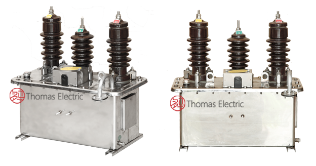
Product Shows

Working Principle
The combined transformer integrates two electromagnetic single-phase voltage transformers and two current transformers within a single oil-filled enclosure. Operating on electromagnetic induction principles, the CT section features toroidal magnetic cores with primary conductors passing through apertures and secondary windings delivering standardized current output. The VT section uses conventional wound construction to step down system voltage to standardized secondary values. The three-phase V/V connection configuration enables accurate measurement of both active and reactive power with reduced component count compared to full three-phase arrangements.
System Application Position
- Rural Distribution Networks: 6-10kV agricultural and rural power distribution systems
- Industrial Substations: Factory and industrial facility distribution stations
- Energy Metering: Revenue-grade electricity measurement for active and reactive power
- Distribution Upgrades: Modernization replacement for traditional separate CT and VT installations
Structural Overview
Oil-immersed construction with integrated moisture-proof device ensures superior insulation performance, thermal management, and extended service life in outdoor environments. The rectangular tank design incorporates lifting lugs for installation handling, oil level indicator, grounding bolt, and drain valve. Complete sealing provides excellent protection against environmental ingress. Internal components are mounted on insulated supports within the tank, with all terminals brought out through sealed bushings.
Model Designation

Model Code Explanation
- J — Combined (integrated) transformer
- L — Current transformer component
- S — Three-phase configuration
- 6, 10 — Voltage class (kV)
Configuration Details
Each JLS-6 or JLS-10 JLSZV-10unit contains two single-phase electromagnetic voltage transformers (PT) and two current transformers (CT), all permanently mounted within a sealed oil-filled rectangular tank. The three-phase V/V connection is achieved through specified terminal connections, providing complete metering capability for three-phase systems with two measurement elements.
Service Conditions
The JLS-6 and JLS-10, JLSZV-10 series combined instrument transformers are designed for outdoor operation in medium-voltage distribution systems under the following service conditions:
- Installation environment: Outdoor installation (pole-mounted or platform-mounted)
- Altitude: Not exceeding 1000 m above sea level (higher altitude requires engineering confirmation and specification adjustment)
- Ambient temperature: Consult factory for specific installation location requirements
- Pollution level: Specify pollution severity for proper selection of external insulation
- Environmental conditions: Designed for outdoor exposure; moisture-proof device protects against humidity ingress
Construction
Construction Design
- Structure: Outdoor pole-type or platform-mounted combined transformer
- Insulation: Oil-immersed with integrated moisture-proof breathing device
- Tank: Rectangular sealed oil tank with lifting lugs
- Components: 2× single-phase VT + 2× CT, electromagnetically coupled
- Connection: Three-phase V/V configuration
- Monitoring: Oil level indicator for visual inspection
- Maintenance: Drain valve and grounding bolt provided
The oil-immersed design provides stable insulation properties, effective thermal management, and resistance to environmental contamination for long-term outdoor service. The integrated moisture-proof device prevents moisture ingress, extending service life beyond conventional designs.
Windings & Terminal Marking

- Current transformer primary terminals: P1 / P2 (per CT section)
- Current transformer secondary terminals: Per nameplate designation
- Voltage transformer primary terminals: Per nameplate designation
- Voltage transformer secondary terminals: Per nameplate designation
Terminal markings follow standard CT and VT polarity conventions. Correct terminal identification and V/V connection wiring shall be observed to ensure metering accuracy and system protection. All secondary circuits must be properly grounded per applicable standards.
Technical Data
This section provides selection-oriented technical data for the JLS-6 and JLS-10 series outdoor oil-immersed combined instrument transformers used in 6 kV and 10 kV class AC distribution systems.
Configuration: Each unit contains two single-phase electromagnetic voltage transformers and two current transformers in three-phase V/V connection, suitable for active and reactive energy metering applications.
Standards Compliance: Combined transformer assembly complies with GB 20840.4-2015. Current transformer sections comply with GB 20840.2-2014 and GB 20840.1-2010. Voltage transformer sections comply with GB 20840.3-2013 and GB 20840.1-2010.
Accuracy Classes Available: 0.2 class and 0.2S class for metering-grade applications.
Customization: Voltage ratio, current ratio, accuracy class, secondary output values, and physical dimensions can be customized based on project requirements.
Standards & Normative References
| Standard | Title | Application |
|---|---|---|
| GB 20840.4-2015 | Instrument Transformers – Part 4: Combined Transformers | Combined transformer requirements |
| GB 20840.2-2014 | Instrument Transformers – Part 2: Additional Requirements for Current Transformers | CT section requirements |
| GB 20840.3-2013 | Instrument Transformers – Part 3: Additional Requirements for Voltage Transformers | VT section requirements |
| GB 20840.1-2010 | Instrument Transformers – Part 1: General Requirements | General requirements for both CT and VT sections |
| IEC 61869-1 | Instrument Transformers – Part 1: General Requirements | International reference standard (where specified) |
| IEC 61869-2 | Instrument Transformers – Part 2: Additional Requirements for Current Transformers | International CT reference (where specified) |
| IEC 61869-3 | Instrument Transformers – Part 3: Additional Requirements for Voltage Transformers | International VT reference (where specified) |
Factory Test Compliance
- Routine tests per applicable GB requirements (including polarity/marking verification, ratio verification, and accuracy verification per specified class)
- Dielectric tests per insulation coordination requirements and applicable standard
- Visual and dimensional inspection including marking, oil level, sealing, and workmanship conformity
- Type and special tests as required by the project specification
- Oil quality verification where specified by project requirements
Installation & Dimensions
- Outline dimensions and mounting details are provided in the dimensional drawings specific to each voltage class.
- The transformer shall be securely mounted using the designated mounting brackets or installation hardware.
- Primary conductor connections shall be made via designated high-voltage terminals or bushings.
- Adequate clearance shall be maintained for insulation, heat dissipation, maintenance access, and oil level inspection.
- Zinc oxide surge arrester must be installed within 1 meter of the transformer installation position for overvoltage protection.
- Before energization, remove the breather plug from the moisture-proof device to activate the breathing function.
Installation Dimensions

Suitable for 6 kV and 10 kV voltage systems. Specific outline dimensions and mounting hole locations are provided in product-specific dimensional drawings.
Safety Notes
- CT secondary circuits must never be left open when the transformer is energized, as dangerous high voltage may appear across the secondary terminals.
- VT secondary circuits shall be properly protected with fuses or circuit breakers to prevent overload or short-circuit damage.
- During inspection or maintenance, the CT secondary circuit shall be short-circuited before disconnecting any instruments.
- One point of each secondary circuit should be reliably grounded in accordance with applicable standards.
- Regularly check oil level indicator and maintain proper oil level.
- Periodically inspect sealing condition and external surface cleanliness.
- All installation and maintenance work shall comply with local electrical safety regulations.
Ordering Information
When placing an order, the required configuration shall be specified according to the local distribution network requirements, applicable standards, and project technical specification. The following parameters shall be clearly stated for technical confirmation and production release:
- Voltage class: JLS-6 (6 kV) or JLS-10 (10 kV)
- Voltage transformer ratio (primary voltage / secondary voltage)
- Current transformer ratio (rated primary current / rated secondary current)
- Accuracy class requirements: 0.2 or 0.2S (specify for both CT and VT sections)
- Secondary output values for both CT and VT sections
- Installation environment: Temperature range, altitude, pollution level
If special requirements apply (e.g., custom voltage/current ratios, high-precision applications, custom physical dimensions, specific appearance requirements, color customization, or enhanced protection ratings), specify them at the ordering stage. Custom configurations shall be confirmed by technical agreement and final data sheet prior to production.