Product Overview
Functional Definition
The JLSW3-10 outdoor oil-immersed three-phase combined instrument transformer (metering unit) is an integrated outdoor metering solution designed for accurate voltage measurement, current measurement, energy metering, and relay protection applications in medium-voltage AC power systems. This combined transformer integrates three single-phase fully-insulated voltage transformers and three current transformers in a single oil-filled enclosure with Y/Y connection configuration for three-phase A-B-C systems.
Key Ratings
| Item | Specification (per order / nameplate) |
|---|---|
| System voltage class | 10 kV class (6 kV variant available); outdoor installation applications |
| Rated frequency | 50 Hz / 60 Hz |
| Voltage transformer configuration | 3 × single-phase fully-insulated PT with Y/Y connection |
| Current transformer configuration | 3 × CT (electromagnetic type) for A, B, C phases |
| Accuracy classes | 0.2 / 0.2S for metering; protection cores as specified |
| PT/CT transformation ratio | As specified in order (customizable) |
| Rated burden | Per core/winding as specified (VA) |
| Insulation structure | Oil-immersed with moisture-prevention device on tank cover |
| Installation environment | Outdoor (substations, industrial distribution, primary-side metering) |
| Applicable standards | GB 20840.4-2015 (combined IT); GB 20840.2-2014 / GB 20840.1-2010 (CT); GB 20840.3-2013 / GB 20840.1-2010 (PT) |
| Lightning protection requirement | Zinc oxide surge arrester required within 1 meter of installation |
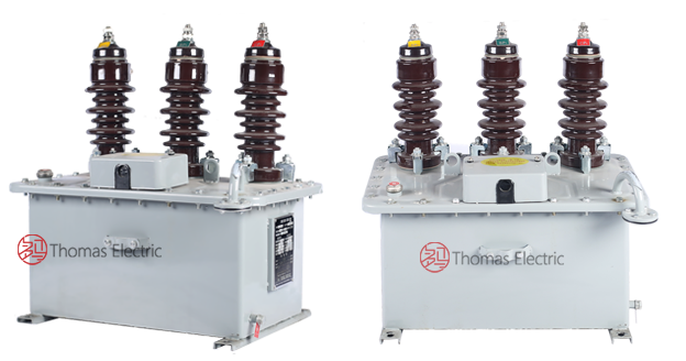
Product Shows

Working Principle
The JLSW3-10 operates on electromagnetic induction principles with integrated voltage and current measurement capabilities. The three single-phase voltage transformers provide proportional secondary voltage signals from the primary system voltage, while the three current transformers deliver standardized secondary current signals proportional to primary line currents. All six transformer elements are mounted on the oil tank base plate and connected to the integrated tank cover assembly, with oil immersion providing superior insulation and thermal performance for outdoor service.
System Application Position
- Outdoor Substations: Urban and rural 6-10kV outdoor distribution substations
- Industrial Power Systems: Mining, manufacturing, and industrial plant distribution networks
- Primary-Side Metering: Revenue-grade energy metering at primary transformer installations
- Protection & Control: Relay protection and SCADA integration in outdoor MV systems
- Combined Metering Units: Integrated PT/CT metering boxes with active and reactive energy meters
Structural Overview
The JLSW3-10 features a compact square oil tank design with enhanced durability and maintenance accessibility for outdoor environments. The tank cover integrates lifting lugs for transportation, oil level gauge for monitoring, grounding bolt for safety, and drain valve for oil servicing. An advanced moisture-prevention device on the tank cover effectively prevents external moisture ingress, extending service life. The design offers higher capacity, lighter weight, and more compact structure compared to traditional configurations, facilitating easier installation in outdoor distribution environments.
Model Designation

Model Code Explanation
- J — Combined instrument transformer (metering unit)
- L — Current transformer component included
- S — Voltage transformer (PT) component included
- W — Outdoor installation type
- 3 — Three-phase configuration (A-B-C phases)
- 10 — Voltage class (kV)
Variant Information
JLSW3-6 and JLSW3-10 variants are available for 6 kV and 10 kV system voltage classes respectively. Both variants support accuracy classes 0.2 and 0.2S for revenue-grade metering applications. Voltage and current transformation ratios, accuracy class combinations, and secondary burdens are specified according to project requirements and system configuration.
Service Conditions
The JLSW3-10 series combined instrument transformers are designed for outdoor operation under normal service conditions in medium-voltage power systems.
- Installation: Outdoor (substations/industrial sites/primary metering points)
- Altitude: ≤1000 m standard; higher altitude on request
- Temperature: Per GB outdoor oil-immersed limits; extremes to be specified
- Humidity: Outdoor moisture-proof/breather protected
- Site condition: Non-corrosive, non-explosive, low vibration/impact
- Lightning: ZnO arrester required within 1 m of the unit
Construction
Construction Design
- Tank structure: Square oil tank design for outdoor service
- Insulation: Oil-immersed insulation system with integrated moisture prevention
- PT configuration: 3 × single-phase fully-insulated electromagnetic voltage transformers
- CT configuration: 3 × electromagnetic current transformers
- Connection: Y/Y three-phase connection for A-B-C phases
- Tank cover features: Lifting lugs, oil level gauge, grounding bolt, drain valve, moisture-prevention device
- Mounting: PT and CT elements securely mounted on tank base plate and integrated with tank cover assembly
The oil-immersed design provides excellent insulation performance, thermal stability, and protection against outdoor environmental conditions. The moisture-prevention device effectively blocks external moisture ingress, ensuring long-term reliability in outdoor installations.
Windings & Terminal Marking

- Primary terminals (PT): High-voltage phase terminals for A, B, C phases
- Primary terminals (CT): P1 / P2 per phase (A, B, C)
- Secondary terminals (PT): Secondary voltage outputs per phase
- Secondary terminals (CT): Secondary current outputs per phase (1S1/1S2 metering, 2S1/2S2 protection where applicable)
- Grounding: Dedicated grounding bolt on tank cover
Terminal markings follow standard instrument transformer polarity conventions. Correct terminal identification and connection shall be observed to ensure proper metering and protection performance. The Y/Y connection configuration must be maintained for three-phase balanced operation.
Technical Data
This section provides selection-oriented technical data for the JLSW3-10 outdoor oil-immersed three-phase combined instrument transformer used in 10 kV class AC systems (50/60 Hz). Data shown below is intended for preliminary selection of PT/CT transformation ratios, accuracy class combinations, and rated burdens.
Definitions: Accuracy class indicates metering and/or protection performance per GB 20840 series standards. Rated burden (VA) is specified per secondary winding. Transformation ratio for both PT and CT components must be specified at ordering.
Notation: Customization available for transformation ratios, accuracy classes, secondary burdens, and insulation levels. Acceptance shall be based on nameplate values and factory test report.
Data Reference
| Parameter | JLSW3-6 | JLSW3-10 |
|---|---|---|
| System voltage class | 6 kV | 10 kV |
| Rated frequency | 50 Hz / 60 Hz | 50 Hz / 60 Hz |
| PT configuration | 3 × single-phase, Y/Y connection | 3 × single-phase, Y/Y connection |
| CT configuration | 3 × electromagnetic type | 3 × electromagnetic type |
| Metering accuracy class | 0.2 / 0.2S | 0.2 / 0.2S |
| PT transformation ratio | Per specification (customizable) | Per specification (customizable) |
| CT transformation ratio | Per specification (customizable) | Per specification (customizable) |
| Secondary output (PT) | Per specification (VA) | Per specification (VA) |
| Secondary output (CT) | Per specification (VA) | Per specification (VA) |
| Insulation structure | Oil-immersed with moisture prevention | Oil-immersed with moisture prevention |
| Installation | Outdoor | Outdoor |
Standards & Normative References
| Standard | Title | Application |
|---|---|---|
| GB 20840.4-2015 | Instrument Transformers – Part 4: Combined Transformers | Combined instrument transformer requirements |
| GB 20840.2-2014 | Instrument Transformers – Part 2: Current Transformers | CT component requirements |
| GB 20840.3-2013 | Instrument Transformers – Part 3: Voltage Transformers | PT component requirements |
| GB 20840.1-2010 | Instrument Transformers – Part 1: General Requirements | General requirements for both PT and CT components |
| IEC 61869-3 | Instrument Transformers – Part 3: Voltage Transformers | International PT reference (where specified) |
| IEC 61869-2 | Instrument Transformers – Part 2: Current Transformers | International CT reference (where specified) |
| IEC 61869-1 | Instrument Transformers – Part 1: General Requirements | International general requirements (where specified) |
| DL/T 866 | Technical Specification for Combined Instrument Transformers | Optional (power industry technical specification) |
Factory Test Compliance
- Routine tests per applicable GB requirements (including polarity/marking verification, ratio verification, and accuracy verification per specified class and burden for both PT and CT components)
- Dielectric tests per insulation coordination requirements and applicable standard
- Oil quality tests per transformer oil specifications and moisture content verification
- Visual and dimensional inspection including marking, workmanship conformity, and moisture-prevention device function
- Type and special tests as required by the project specification
Installation & Dimensions
- Outline dimensions and mounting details are provided in the dimensional drawings per voltage class variant.
- The combined transformer shall be securely mounted using the designated base mounting provisions.
- Primary connections for both PT and CT shall be made per the connection diagram and terminal marking.
- Adequate clearance shall be maintained for insulation, heat dissipation, oil level monitoring, and maintenance access.
- Zinc oxide surge arrester must be installed within 1 meter of the combined transformer for lightning protection.
- Before energization, remove the unsealed breather element from the central buffer rubber of the moisture-prevention device to ensure proper transformer operation.
Outlines

Safety Notes
- PT secondary circuit should be equipped with appropriate fuses and one point reliably grounded.
- CT secondary circuit must never be left open when the transformer is energized, as dangerous high voltage may appear across the secondary terminals.
- During inspection or maintenance, CT secondary circuits shall be short-circuited before disconnecting any instruments.
- One point of each CT secondary circuit should be reliably grounded in accordance with applicable standards.
- Monitor oil level regularly using the integrated oil level gauge.
- Maintain external cleanliness and inspect sealing integrity and moisture-prevention device function periodically.
- All installation and maintenance work shall comply with local electrical safety regulations and GB standards.
Ordering Information
When placing an order, the required configuration shall be specified according to the local grid requirements, applicable standards, and project technical specification. The following parameters shall be clearly stated for technical confirmation and production release:
- System voltage class (6 kV or 10 kV)
- PT transformation ratio (voltage ratio for three-phase system)
- CT transformation ratio (current ratio for A, B, C phases)
- Accuracy class requirements (0.2 / 0.2S for metering; protection cores if applicable)
- Rated burden (VA) for PT and CT secondary windings
- Secondary output configuration (specify if active/reactive energy meters will be integrated)
- Insulation level (specify if non-standard altitude or environmental conditions apply)
- Customization requirements (special appearance, special ratios, high-precision versions, or non-standard configurations)
- Operating environment conditions (altitude, temperature range, humidity, pollution level for proper rating confirmation)
If local utility or project requirements apply (e.g., special insulation level, terminal arrangement, mounting constraints, documentation language, or required certificates), specify them at the ordering stage. Special configurations shall be confirmed by technical agreement and final data sheet prior to production.