Product Overview
Functional Definition
The JLSW3-35kV outdoor oil-immersed combined instrument transformer (also designated as metering box) is a three-phase high-voltage energy metering assembly designed for outdoor installation in AC power systems up to 35 kV. This integrated package combines three single-phase fully-insulated voltage transformers (VT/PT) configured in Y/Y connection with three current transformers (CT) installed on phases A, B, and C respectively, providing simultaneous current and voltage measurement in a single oil-filled enclosure.
This design represents an optimized upgrade from conventional configurations, featuring an integrated moisture-proof device in the tank cover to prevent external humidity ingress and extend service life. Compared to legacy models, the JLSW3-35kV offers increased capacity, reduced dimensions, lower weight, and simplified installation procedures.
Key Ratings
| Item | Specification (per order / nameplate) |
|---|---|
| System voltage class | 35 kV (outdoor distribution and substation applications) |
| Rated frequency | 50 Hz / 60 Hz |
| Configuration | 3 × single-phase VT (Y/Y connection) + 3 × CT (one per phase) |
| VT connection | Y/Y (three single-phase fully-insulated voltage transformers) |
| CT configuration | One electromagnetic CT per phase (A, B, C) |
| Accuracy classes | 0.2 / 0.2S (metering cores per specification) |
| Insulation type | Oil-immersed |
| Installation environment | Outdoor |
| Optional metering | Active / reactive energy meter integration available |
| Applicable standards | GB 20840.4-2015; GB 20840.2-2014; GB 20840.1-2010; GB 20840.3-2013 |
| Lightning protection | Zinc oxide arrester required within 1 m of installation location |
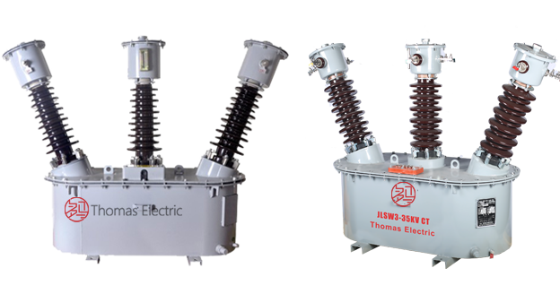
Product Shows

Working Principle
Voltage Transformer (VT) Section: Three single-phase electromagnetic voltage transformers operate on electromagnetic induction principles to step down primary high voltage (35 kV class) to standardized secondary voltage (typically 100 V or 100/√3 V) for metering and monitoring applications. The Y/Y connection configuration provides phase voltage measurement with grounded neutral point.
Current Transformer (CT) Section: Three electromagnetic current transformers feature toroidal magnetic cores with primary conductors passing through the aperture and secondary windings wound around the cores. Magnetic flux generated by primary current induces proportional voltage in the secondary windings, delivering standardized output current (1 A or 5 A) through connected burden.
System Application Position
- Rural Substations: Energy metering in 35 kV rural distribution networks
- Box-Type Substations: Compact metering installations in prefabricated substation units
- Power Plants: Generator and auxiliary system metering applications
- Industrial Distribution: Plant and factory 35 kV switchgear metering
- Revenue Metering: Utility billing and energy accounting systems
- SCADA Integration: Remote monitoring and control system interface
Structural Overview
The combined transformer assembly consists of three single-phase voltage transformers and three current transformers, all electromagnetic type, mounted on fixed terminal plates within a rectangular oil-filled tank. The tank cover is securely fastened and equipped with two lifting lugs for hoisting during installation. The compact rectangular tank design incorporates oil level gauge, grounding bolt, and oil drain valve on the side panel for outdoor service requirements.
The integrated moisture-proof device in the tank cover prevents humidity penetration into the oil, protecting internal components from moisture degradation and extending operational life compared to conventional designs.
Model Designation

Model Code Explanation
- J — Combined instrument transformer (metering box)
- L — Current transformer element
- S — Voltage transformer element (three-phase)
- W — Outdoor installation
- 3 — Three-phase configuration
- 35 — Voltage class (kV)
Service Conditions
The JLSW3-35kV combined instrument transformer is designed for outdoor installation under normal service conditions in high-voltage distribution systems.
- Installation environment: Outdoor installation
- Altitude: Not exceeding 1000 m above sea level (higher altitude installations require engineering confirmation and rating adjustment)
- Ambient temperature: −25 °C to +40 °C (extended range available upon specification)
- Relative humidity: Daily average ≤ 95%, monthly average ≤ 90% (at +20 °C reference)
- Pollution level: Per IEC 60815 / GB/T 26218 as specified by project requirements
- Environmental conditions: Free from corrosive gases or vapors; free from explosive or flammable media; no severe vibration, mechanical shock, or salt spray (coastal installations require additional protection)
- Seismic requirements: Per applicable regional seismic design standards where specified
Construction
Construction Design
- Structure: Integrated oil-filled tank assembly with combined VT and CT elements
- Insulation: Oil-immersed insulation system for both VT and CT sections
- VT core: Three single-phase electromagnetic voltage transformer cores
- CT core: Three ring-type electromagnetic current transformer cores
- Tank construction: Rectangular welded steel tank with moisture-proof cover
- Mounting: Fixed terminal plates for VT and CT assembly; lifting lugs for installation
- Accessories: Oil level gauge, grounding bolt, drain valve, breathing apparatus
The oil-immersed design provides superior insulation performance, thermal management, and environmental protection for long-term outdoor service. The integrated moisture-proof device in the tank cover actively prevents humidity ingress, a critical improvement over conventional designs in humid climates.
Windings & Terminal Marking

Voltage Transformer Terminals:
- Primary terminals (per phase): A-X, B-X, C-X (where X is grounded neutral point)
- Secondary terminals (per phase): a-x, b-x, c-x (where x is grounded neutral point)
- Connection: Y/Y configuration with grounded neutral
Current Transformer Terminals:
- Phase A CT: P1A / P2A (primary), S1A / S2A (secondary)
- Phase B CT: P1B / P2B (primary), S1B / S2B (secondary)
- Phase C CT: P1C / P2C (primary), S1C / S2C (secondary)
Terminal markings follow standard polarity conventions per GB 20840 series. Under normal operating conditions, the reference current direction is defined from P1 to P2, with corresponding secondary current from S1 to S2. Correct terminal identification shall be observed to ensure accurate metering and protection performance.
Technical Data
This section provides selection-oriented technical data for the JLSW3-35kV outdoor oil-immersed combined instrument transformer used in 35 kV class AC systems (50 Hz / 60 Hz). Data shown below is intended for preliminary selection of voltage and current ratios, accuracy class combinations, and rated burdens.
Definitions:
- Voltage ratio: Primary to secondary voltage transformation ratio for VT section (e.g., 35000/100, 35000/√3/100/√3)
- Current ratio: Primary to secondary current transformation ratio for CT section (e.g., 50/5, 100/5, 200/5)
- Accuracy class: Metering accuracy classification per GB 20840 (e.g., 0.2, 0.2S for revenue metering)
- Rated burden (VA): Maximum load that can be connected to secondary circuits while maintaining specified accuracy
- Secondary current: Standardized output current (1 A or 5 A) for CT section
Data Reference
Voltage Transformer (VT) Section – Typical Ratings
| Rated Primary Voltage (V) |
Rated Secondary Voltage (V) |
Accuracy Class |
Rated Burden (VA) |
Burden Power Factor |
|---|---|---|---|---|
| 35000/√3 | 100/√3 | 0.2 | 50 | cosφ = 0.8 (lagging) |
| 35000/√3 | 100/√3 | 0.2S | 50 | cosφ = 1.0 |
| 35000 | 100 | 0.2 | 50 | cosφ = 0.8 (lagging) |
| 35000 | 100 | 0.2S | 50 | cosφ = 1.0 |
Current Transformer (CT) Section – Typical Ratings
| Rated Primary Current (A) |
Rated Secondary Current (A) |
Accuracy Class |
Rated Burden (VA) |
Burden Power Factor |
|---|---|---|---|---|
| 50 | 5 | 0.2 | 10 | cosφ = 0.8 (lagging) |
| 75 | 5 | 0.2 | 10 | cosφ = 0.8 (lagging) |
| 100 | 5 | 0.2 | 10 | cosφ = 0.8 (lagging) |
| 150 | 5 | 0.2 | 15 | cosφ = 0.8 (lagging) |
| 200 | 5 | 0.2 | 15 | cosφ = 0.8 (lagging) |
| 300 | 5 | 0.2 | 15 | cosφ = 0.8 (lagging) |
| 400 | 5 | 0.2 | 20 | cosφ = 0.8 (lagging) |
| 600 | 5 | 0.2 | 20 | cosφ = 0.8 (lagging) |
Standards & Normative References
| Standard | Title | Application |
|---|---|---|
| GB 20840.4-2015 | Instrument Transformers – Part 4: Combined Transformers | Primary product standard for combined instrument transformers |
| GB 20840.2-2014 | Instrument Transformers – Part 2: Current Transformers | CT-specific requirements (aligned with IEC 61869-2) |
| GB 20840.1-2010 | Instrument Transformers – Part 1: General Requirements | General requirements for both VT and CT sections |
| GB 20840.3-2013 | Instrument Transformers – Part 3: Voltage Transformers | VT-specific requirements (aligned with IEC 61869-3) |
| IEC 61869-1 | Instrument Transformers – Part 1: General Requirements | International reference (GB 20840.1 aligned) |
| IEC 61869-2 | Instrument Transformers – Part 2: Current Transformers | International CT reference (GB 20840.2 aligned) |
| IEC 61869-3 | Instrument Transformers – Part 3: Voltage Transformers | International VT reference (GB 20840.3 aligned) |
| GB/T 26218 | Pollution Severity and External Insulation for High-Voltage Equipment | Outdoor insulation coordination for pollution environments |
| IEC 60815 | Selection and Dimensioning of High-Voltage Insulators – Polluted Conditions | International pollution level reference |
Factory Test Compliance
Voltage Transformer (VT) Tests:
- Routine tests per GB 20840.3: Polarity verification, ratio verification, voltage error and phase displacement at specified burdens and voltages
- Dielectric withstand tests: Power-frequency withstand voltage, impulse voltage (lightning and switching impulse where applicable)
- Partial discharge test where specified by project requirements
- Visual and dimensional inspection including terminal marking
Current Transformer (CT) Tests:
- Routine tests per GB 20840.2: Polarity verification, ratio verification, current error and phase displacement at specified burdens and currents
- Dielectric withstand tests: Power-frequency withstand voltage on primary and secondary circuits
- Visual and dimensional inspection including terminal marking
Combined Assembly Tests:
- Oil quality tests: Dielectric strength, moisture content, acidity
- Tank leak test: Pressure test or vacuum leak detection
- Integrated function verification: Simultaneous VT and CT operation confirmation
- Type and special tests as required by project specification
Installation & Dimensions
- Outline dimensions and mounting details are provided in the dimensional drawings specific to JLSW3-35kV configuration.
- The combined transformer assembly shall be securely mounted on a stable foundation or supporting structure using the designated mounting points.
- Primary connections for VT section are made via high-voltage bushing terminals.
- Primary connections for CT section are made via through-type busbar or bolted terminals.
- Adequate clearance shall be maintained for insulation coordination, heat dissipation, oil level inspection, and maintenance access.
- Lightning protection (zinc oxide arrester) shall be installed within 1 meter of the transformer location per GB standards.
Outlines
JLSW3-35kV Combined Transformer Assembly

Safety Notes
- CT secondary circuits: Secondary circuits must never be left open when the transformer is energized, as dangerous high voltage may appear across the secondary terminals.
- VT secondary fusing: Secondary circuits shall be protected with appropriate fuses per project electrical protection coordination.
- Grounding: One point of each secondary circuit (VT neutral and CT secondary) shall be reliably grounded in accordance with GB 50065 and local electrical safety regulations.
- Lightning protection: Zinc oxide arrester installation within 1 m is mandatory per GB 20840.4-2015 requirements.
- Maintenance procedures: During inspection or maintenance, CT secondary circuits shall be short-circuited before disconnecting any instruments. De-energize VT primary before secondary circuit work.
- Oil handling: Follow environmental regulations for oil handling, storage, and disposal. Maintain oil level per manufacturer specifications.
- All installation and maintenance work shall comply with local electrical safety regulations and utility standards.
Ordering Information
When placing an order, the required configuration shall be specified according to the local grid requirements, applicable standards, and project technical specification. The following parameters shall be clearly stated for technical confirmation and production release:
Voltage Transformer (VT) Specification:
- Rated primary voltage / voltage ratio (e.g., 35000/100 V or 35000/√3/100/√3 V)
- Accuracy class for metering application (e.g., 0.2, 0.2S)
- Rated burden (VA) for secondary circuit
- Secondary winding configuration (single secondary or dual secondary if required)
Current Transformer (CT) Specification:
- Rated primary current / transformation ratio (e.g., 100/5 A, 200/5 A)
- Rated secondary current (1 A or 5 A, specify for each phase if different)
- Accuracy class for metering application (e.g., 0.2, 0.2S)
- Rated burden (VA) for secondary circuit
Environmental and Installation Specification:
- Altitude (if exceeding 1000 m)
- Pollution level per IEC 60815 / GB/T 26218
- Ambient temperature range (if outside standard -25°C to +40°C)
- Special environmental conditions (coastal, high humidity, seismic, etc.)
Optional Configuration:
- Active and/or reactive energy meter integration
- Communication interface for remote metering (Modbus, IEC 61850, etc.)
- Special terminal arrangements or connection configurations
- Factory acceptance test (FAT) requirements
- Documentation language and certification requirements
Selection Guidance: Determine VT ratio based on system nominal voltage (35 kV). Select CT ratio from expected load current range ensuring adequate measurement range while maintaining accuracy at minimum load. For revenue metering, select 0.2S or 0.2 accuracy class per utility requirements and GB 17215 series. Calculate rated burdens as sum of connected instrument burden plus wiring losses based on cable length and cross-section. Verify environmental suitability (ambient temperature range, altitude, pollution level) against product service conditions and specify enhanced ratings if required. Special configurations shall be confirmed by technical agreement and final data sheet prior to production.