Product Overview
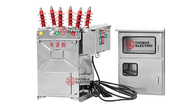
The JLSZK-12 IV high-voltage prepaid metering box is an outdoor integrated measurement and control unit that combines a ZW8-12 vacuum circuit breaker (VCB) with built-in voltage transformer (VT/PT) and current transformer (CT) assemblies within a single weather-resistant enclosure. The unit is intended for three-phase 50 Hz medium-voltage distribution systems with rated system voltage of 6 kV or 10 kV, with equipment rated voltage class Um 12 kV. It provides revenue metering signal outputs, prepaid load control (remote disconnect/restore), and feeder protection switching capability in applications such as rural overhead distribution, pole-mounted or station boundary metering points, industrial feeder sections, and distributed generation interconnection metering/control nodes.
 Thomas Electric")
Key Ratings
| Item | Specification (per order / nameplate) |
|---|---|
| System voltage / rated voltage class | Applicable system: 6 kV or 10 kV; equipment class: Um 12 kV (outdoor distribution) |
| Rated frequency | 50 Hz |
| Rated current | 630 A |
| CT ratio | Multi-ratio CT within 5–800/5 A range (secondary 5 A standard; 1 A available upon request) |
| PT ratio | Standard: 10000/100 V (additional ratios for 6 kV systems available upon request) |
| Accuracy classes | PT: 0.2 class (metering); CT: 0.2S class (metering) |
| Rated burden | PT: 2×20 VA; CT: 2×10 VA (per winding/core as specified) |
| Rated short-circuit breaking current | 12.5 / 16 / 20 kA (VCB, per configuration) |
| Rated short-circuit making current (peak) | 31.5 / 40 / 40 kA (peak, per configuration) |
| Rated peak withstand current | 31.5 / 40 / 50 kA (dynamic) |
| Rated short-time withstand current | 12.5 / 16 / 20 kA, 4 s |
| Control voltage | AC/DC 110 V or 220 V (opening/closing circuits, per order) |
| Applicable standards | GB 1207-2006, GB 1208-2006, GB 17201-2007, GB 1984-2003, DL/T 403, IEC 56 |
Working Principle
The JLSZK-12 IV integrates three functional subsystems: (1) the vacuum circuit breaker provides switching and fault interruption capability; (2) the CT and VT provide galvanically isolated measurement signals for revenue metering and monitoring; (3) the prepaid control logic performs energy accounting and executes load control commands, including remote disconnect and restore. The CT and VT operate on electromagnetic induction principles to maintain specified ratio and phase accuracy within the rated burden limits. The VCB employs a spring-stored energy mechanism that supports electrically commanded operation and local manual operation as permitted by the mechanism design, enabling operational continuity under auxiliary power constraints when manual operation is selected and safety conditions allow.
System Application Position
- Rural Distribution Networks: 6–10 kV overhead line metering points with prepaid disconnect function
- Substation / Boundary Metering: Medium-voltage revenue metering and sectional load management
- Distributed Generation: PV/wind interconnection metering and controllable point of connection
- Industrial Feeders: Facility feeders requiring prepaid energy control and switching isolation
Structural Overview
The unit adopts a three-phase common-enclosure configuration integrating the operating mechanism, primary conductive circuit, insulation and sealing system, and CT/VT assemblies. The insulation scheme is oil-free and designed for outdoor service, utilizing vacuum interruption technology for switching and epoxy resin sealing/casting for instrument transformer insulation and environmental protection. The housing is stainless steel or galvanized aluminum with anti-corrosion treatment, providing weather resistance suitable for outdoor installation under specified pollution grade and climatic conditions.
Model Designation
 Thomas Electric")
Code Explanation
JLSZK-12-F (JLSZK-12 IV)
- J — Voltage transformer (VT/PT) function integrated
- L — Current transformer (CT) function integrated
- S — Three-phase configuration
- Z — Dry-type insulation structure (oil-free)
- K — Vacuum switching device integrated (vacuum circuit breaker platform)
- 12 — Rated voltage class Um 12 kV (applicable to 6–10 kV systems)
- F — Prepaid metering and load control function (remote disconnect capable)
The model designation identifies an outdoor integrated prepaid metering and switching unit combining VT, CT, and a vacuum switching device in a three-phase dry-type structure. The suffix code represents the functional configuration; CT/PT ratios, accuracy classes, burdens, control voltage, and communication interface shall be specified per project requirements and confirmed by the supplied nameplate and test documentation.
Construction
Construction Design
- Structure: Outdoor integrated three-phase common-box design
- Circuit breaker: ZW8-12 vacuum interrupter with spring-stored energy operating mechanism
- Insulation system: Oil-free insulation coordination using sealed structure and epoxy resin protection for instrument transformers
- Housing material: Stainless steel or galvanized aluminum with anti-corrosion treatment
- Control interface: Observation/inspection window and safety isolation provisions as configured
- Operating capability: Electrical open/close with auxiliary control supply; local operation per mechanism design and safety interlocks
Windings & Terminal Marking
- PT primary terminals: Three-phase voltage input terminals (A/B/C per wiring diagram)
- PT secondary terminals: Metering output terminals (standard ratio 10000 V/100 V per nameplate)
- CT primary conductor: Primary current path rated for 5–800 A class selection (tapped/multi-ratio per design)
- CT secondary terminals (Group 1): 1S1 / 1S2 (metering core 0.2S)
- CT secondary terminals (Group 2): 2S1 / 2S2 (metering core 0.2S)
Terminal marking and polarity follow instrument transformer conventions. Correct polarity and circuit identification shall be maintained during wiring to ensure metering accuracy and correct functional operation. CT secondary circuits shall be protected and handled in accordance with safety requirements; do not open-circuit CT secondary when the primary is energized.
Service Conditions
The JLSZK-12 IV high-voltage prepaid metering box is designed for outdoor installation in medium-voltage distribution systems under the service conditions stated below. For conditions beyond these limits, engineering confirmation and special design measures shall be agreed during ordering.
Installation Environments
- Installation environment: Outdoor installation with weather-resistant enclosure
- System compatibility: 6 kV or 10 kV three-phase 50 Hz AC systems; Um 12 kV equipment class
- Altitude: ≤2000 m above sea level
- Ambient temperature: −35°C to +40°C
- Relative humidity: Daily average ≤90%, monthly average ≤90%
- Water vapor pressure: Daily ≤2.2 kPa, monthly ≤1.8 kPa
- Seismic resistance: ≤8 degree earthquake intensity
- Pollution level: Grade III
- Environmental exclusions: No fire hazard, explosive atmosphere, chemical corrosion, or severe vibration beyond design limits
Technical Data
Data Reference
| No. | Item | Unit | Value |
|---|---|---|---|
| 1 | Rated voltage class (Um) | kV | 12 |
| 2 | Rated current | A | 630 |
| 3 | Power frequency withstand voltage | kV | 42 |
| 4 | Lightning impulse withstand voltage (peak) | kV | 75 |
| 5 | Rated short-circuit breaking current | kA | 12.5 / 16 / 20 |
| 6 | Rated short-circuit making current (peak) | kA | 31.5 / 40 / 40 |
| 7 | Rated peak withstand current (dynamic) | kA | 31.5 / 40 / 50 |
| 8 | Rated short-time withstand current | kA | 12.5 / 16 / 20 |
| 9 | Rated short-time withstand duration | s | 4 |
| 10 | Operating sequence | — | O-0.3s-CO-180s-CO |
| 11 | Rated short-circuit breaking operations | cycles | 30 |
| 12 | Mechanical life | operations | 10000 |
| 13 | Charging / control voltage | V | AC/DC 110, 220 |
| 14 | Operating voltage – Opening coil | V | AC/DC 110, 220 |
| 15 | Operating voltage – Closing coil | V | AC/DC 110, 220 |
| 16 | Overcurrent trip current | A | 5 |
| 17 | Static contact allowable compression | mm | 3 |
| 18 | Total weight | kg | 150 |
Transformer Ratings
| PT Rated Voltage Ratio (V) |
CT Rated Current Ratio (A) |
PT Accuracy |
CT Accuracy |
PT Output (VA) |
CT Output (VA) |
|---|---|---|---|---|---|
| 10000/100 | 5~800/5 | 0.2 | 0.2S | 2×20 | 2×10 |
Standards & Normative References
The JLSZK-12 IV high-voltage prepaid metering box is designed and manufactured in accordance with the following standards or their applicable provisions. Where project requirements specify alternative editions or additional standards, compliance shall be confirmed by technical agreement and documentation.
- GB 1207-2006: Voltage Transformers
- GB 1208-2006: Current Transformers
- GB 311.1-1997: Insulation Co-ordination for High-Voltage Electrical Equipment
- GB 17201-2007: Combined Instrument Transformers
- GB 1984-2003: AC High-Voltage Circuit Breakers
- GB/T 11022-89: Common Technical Requirements for High Voltage Switchgear and Controlgear
- DL/T 403: Technical Specifications for 12–40.5 kV High Voltage Vacuum Circuit Breakers
- IEC 56: High-Voltage Alternating-Current Circuit Breakers
Factory Test Compliance
- Instrument transformer accuracy verification: Ratio, phase displacement, burden verification per GB 1207-2006 and GB 1208-2006
- Circuit breaker mechanical operation test: Spring charging, close/open sequences, interlock verification as applicable
- Insulation resistance measurement: Primary and secondary circuits
- Power frequency withstand voltage test: 42 kV, 1 minute (as specified)
- Lightning impulse withstand test: 75 kV peak where specified
- Visual and dimensional inspection: Marking, nameplate, workmanship, enclosure sealing condition
- Functional testing: Metering signal output, control logic, remote disconnect/restore function per configured interface
- Type and special tests: As required by project specification and applicable standards
Installation & Dimensions
 Thomas Electric")
- Outline dimensions and mounting details are provided in the dimensional drawings supplied with the unit.
- The metering box shall be securely mounted using designated fixing holes and outdoor-rated corrosion-resistant hardware.
- Primary connections shall be made using outdoor-rated insulated conductors, terminals, or bus connections in accordance with site practice.
- Required electrical clearances and safety distances shall be maintained for insulation coordination and safe operation.
- Control wiring and communication cables shall be routed through designated sealed entries to maintain enclosure protection performance.
Ordering Information
When placing an order, the required configuration shall be specified according to local utility requirements, applicable standards, and the project technical specification. The following parameters shall be clearly stated for technical confirmation and production release:
- System voltage: 6 kV or 10 kV (equipment class Um 12 kV)
- Rated current: 630 A or other (specify)
- CT configuration: Primary ratio selection, secondary 1 A or 5 A, accuracy class, burden (VA)
- PT configuration: Voltage ratio, accuracy class, burden (VA), and any auxiliary winding requirement
- Short-circuit ratings: Breaking current, making current, peak withstand, short-time withstand and duration, aligned to system prospective fault level
- Control voltage: AC/DC 110 V or 220 V
- Communication interface: GSM module or other interface; protocol requirements for the utility metering management system
- Prepaid functionality: Credit management integration requirements and remote disconnect/restore logic
- Environmental requirements: Altitude, temperature range, pollution level, seismic rating, corrosion class
- Enclosure customization: Material, coating, non-standard dimensions, and identification labeling requirements
- Documentation and certification: Test certificates, type test reports, and required document language