Product Overview
Functional Definition
The JLSZV-10kV three-phase outdoor combined instrument transformer is a precision electromagnetic metering instrument designed for accurate voltage and current measurement, energy metering, and system monitoring in medium-voltage AC power systems. This combined unit integrates three single-phase dry-type voltage transformers (VTs) configured in V/V connection with three current transformers (CTs), providing galvanically isolated secondary signals proportional to primary voltage and current in outdoor distribution applications.
Key Ratings
| Item | Specification (per order / nameplate) |
|---|---|
| System voltage class | 6 kV / 10 kV class (outdoor distribution and grid transformation applications) |
| Rated frequency | 50 Hz (60 Hz available upon request) |
| VT configuration | V/V connection (three single-phase units) |
| Rated secondary voltage (VT) | 100 V |
| VT accuracy classes | 0.2 / 0.5 (metering application) |
| VT rated output | 2 × 15 VA (0.2 class) / 2 × 30 VA (0.5 class) |
| CT rated secondary current | 1 A, 2 A, or 5 A (as specified) |
| CT accuracy class | As specified per application requirement |
| CT rated burden | Per core/winding as specified (VA) |
| CT short-circuit withstand | Ith (1 s) and Idyn (peak) as specified |
| Insulation level | 1.2/42/75 kV (power frequency / lightning impulse / switching impulse) |
| Minimum creepage distance | 440 mm |
| Insulation material | Epoxy resin cast (vacuum-cast outdoor-grade construction) |
| Installation environment | Outdoor (pollution-resistant, maintenance-free design) |
| Applicable standards | IEC 61869-1/-2/-3; GB/T 20840 series; DL/T 866 |
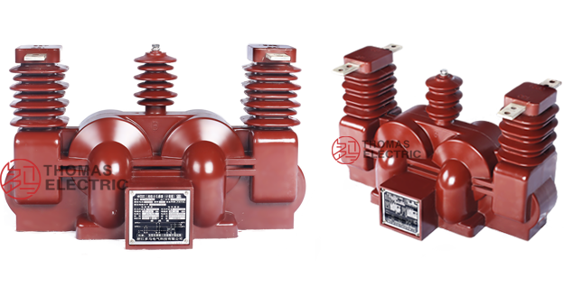
Product Shows

Working Principle
The JLSZV-10kV combined instrument transformer operates on electromagnetic induction principles for both voltage and current transformation. The voltage transformer section employs three single-phase dry-type VTs in V/V connection, providing two-phase voltage measurement capability for three-phase systems. Each VT features a laminated silicon-steel core with primary and secondary windings designed for accurate voltage ratio transformation. The current transformer section utilizes toroidal magnetic cores with primary conductors passing through the core apertures and secondary windings wound around the cores, delivering standardized current signals proportional to primary current through connected burdens. The epoxy resin cast insulation provides superior outdoor performance with high pollution resistance and long-term stability.
System Application Position
- Grid Transformation Projects: Rural and urban distribution network modernization programs replacing oil-immersed equipment
- Medium Voltage Distribution: 6-10kV outdoor switchgear, distribution panels, and ring main units
- Energy Metering Systems: Revenue-grade electricity measurement for substations and distribution points
- Industrial Power Monitoring: Factory and facility power quality monitoring and load management
- Renewable Integration: Solar and wind farm collection systems requiring compact outdoor metering
Structural Overview
Fully-enclosed epoxy resin vacuum-cast construction ensures exceptional insulation performance, moisture resistance, pollution resistance, and mechanical strength for outdoor service. The combined unit integrates three-phase voltage transformers in V/V configuration with adjustable-tap current transformers in a compact pole-mounted or ground-mounted package. The maintenance-free design requires only periodic external surface cleaning, eliminating oil maintenance and environmental concerns associated with traditional oil-immersed equipment. The outdoor-grade epoxy casting provides UV resistance, weathering resistance, and long-term dielectric stability under varying environmental conditions.
Model Designation

Model Code Explanation
- J — Combined instrument transformer (voltage + current)
- L — Current transformer component
- S — Three-phase configuration
- Z — Outdoor support (pillar/post) type mounting
- V — Voltage transformer component with V/V connection
- 10 — Voltage class (kV) – applicable for 6 kV and 10 kV systems
Configuration Options
JLSZV-10kV units are configured based on system voltage (6 kV or 10 kV), primary current ratings, VT and CT accuracy class requirements, and burden specifications. The CT section features adjustable secondary winding taps for precise current ratio adjustment, enabling fine-tuning to match actual system conditions and metering accuracy requirements. VT section maintains fixed 100V secondary output with selectable accuracy class and burden capacity based on connected metering equipment.
Service Conditions
The JLSZV-10kV combined instrument transformer is designed for outdoor operation under normal service conditions in medium-voltage power distribution systems.
- Installation environment: Outdoor installation (pollution-resistant epoxy resin construction)
- Altitude: Not exceeding 1000 m above sea level (higher altitude ratings available upon specification for engineering confirmation)
- Ambient temperature: −25 °C to +45 °C (outdoor service range)
- Relative humidity: Daily average ≤ 95%, monthly average ≤ 90% (at +20 °C reference)
- Pollution level: Suitable for moderate to heavy pollution environments (creepage distance 440 mm minimum)
- Environmental conditions: Resistant to UV radiation, rain, snow, ice, and atmospheric pollution; no explosive or flammable atmosphere; designed for typical outdoor distribution system conditions
- Seismic conditions: Earthquake resistance per local grid requirements (shall be specified at ordering)
Construction
Construction Design
- Structure: Outdoor support (post) type for pole mounting or ground mounting
- Insulation: Fully enclosed epoxy resin vacuum-cast insulation (outdoor-grade formulation)
- VT core: Laminated silicon-steel core for voltage transformer section
- CT core: Toroidal magnetic core for current transformer section
- System: Integrated three-phase voltage and current measurement in single assembly
- Environmental protection: UV-resistant, pollution-resistant, weathering-resistant epoxy formulation
- Maintenance: Maintenance-free design requiring only periodic external cleaning
The epoxy resin vacuum casting process ensures void-free insulation with excellent dielectric properties, mechanical strength, and long-term stability. The outdoor-grade formulation provides superior resistance to environmental aging, thermal cycling, moisture ingress, and surface contamination compared to traditional porcelain or oil-immersed designs.
Windings & Terminal Marking

Current Transformer Section:
- Primary terminals (Phase A): A1 / A2
- Primary terminals (Phase B): B1 / B2
- Primary terminals (Phase C): C1 / C2
- Secondary terminals (adjustable tap): Terminal block with tap selection capability for current ratio adjustment
Voltage Transformer Section (V/V Connection):
- Primary terminals (VT1): A / N
- Primary terminals (VT2): B / N
- Secondary terminals (VT1): a / n
- Secondary terminals (VT2): b / n
Terminal markings follow standard instrument transformer polarity conventions per IEC 61869 and GB/T 20840 series. Under normal operating conditions, reference current direction is defined from primary terminal “1” to “2” for CT sections, and voltage polarity from lettered terminal to neutral for VT sections. Correct terminal identification and polarity observation are essential for accurate metering and system protection performance.
Technical Data
This section provides selection-oriented technical data for the JLSZV-10kV three-phase outdoor combined instrument transformer used in 6 kV and 10 kV class AC distribution systems (50 Hz). Data shown below is intended for preliminary selection of VT accuracy class, CT accuracy class, rated burdens, and short-circuit withstand capability.
Definitions: VT accuracy class indicates voltage measurement precision for metering applications. VT rated output is the maximum burden (VA) that the voltage transformer can supply while maintaining specified accuracy. CT accuracy class indicates current measurement precision. CT rated output is specified per secondary core (VA). Ith is the rated short-time thermal current (typically 1 s) for CT section. Idyn is the rated dynamic current (peak) for CT section.
Notation: Ith/Idyn may be expressed as kA or as multiples of rated primary current (×In) depending on configuration; acceptance shall be based on nameplate values and factory test report.
Voltage Transformer Technical Data
| Item | Specification |
|---|---|
| Configuration | V/V connection (three single-phase units, two active phases) |
| Rated secondary voltage | 100 V |
| Accuracy class 0.2 | Rated output: 2 × 15 VA |
| Accuracy class 0.5 | Rated output: 2 × 30 VA |
| Insulation level | 1.2/42/75 kV |
| Creepage distance | ≥ 440 mm |
Data Reference
| Rated Primary Current Range (A) |
Rated Short-Time Thermal Current (Ith) (kA RMS) |
Rated Dynamic Current (Idyn) (kA peak) |
Rated Secondary Output (VA) |
|---|---|---|---|
| 5 – 10 | 1.0 | 2.5 | 10 |
| 10 – 20 | 1.5 | 3.75 | 10 |
| 15 – 30 | 2.4 | 6.0 | 10 |
| 20 – 40 | 3.0 | 7.5 | 10 |
| 30 – 60 | 4.5 | 11 | 10 |
| 40 – 75 | 8.0 | 20 | 10 |
| 50 – 100 | 9.0 | 22.5 | 10 |
| 75 – 150 | 12 | 30 | 10 |
| 100 – 200 | 16 | 40 | 10 |
| 150 – 300 | 24 | 60 | 10 |
| 200 – 400 | 32 | 80 | 10 |
| 300 – 600 | 60 | 100 | 10 |
| 400 – 800 | 80 | 100 | 10 |
| 500 – 1000 | 80 | 100 | 10 |
Standards & Normative References
| Standard | Title | Application |
|---|---|---|
| IEC 61869-1 | Instrument Transformers – Part 1: General Requirements | General requirements for both VT and CT sections |
| IEC 61869-2 | Instrument Transformers – Part 2: Additional Requirements for Current Transformers | CT-specific requirements |
| IEC 61869-3 | Instrument Transformers – Part 3: Additional Requirements for Inductive Voltage Transformers | VT-specific requirements |
| GB/T 20840.1 | Instrument Transformers – Part 1: General Requirements | National standard (aligned with IEC 61869 framework) |
| GB/T 20840.2 | Instrument Transformers – Part 2: Current Transformers | National CT requirements |
| GB/T 20840.3 | Instrument Transformers – Part 3: Voltage Transformers | National VT requirements |
| DL/T 866 | Technical Specification for Dry-Type Combined Instrument Transformers | Industry specification for combined transformer design and application |
| GB 311.1 | Insulation Co-ordination – Part 1: Definitions, Principles and Rules | Insulation coordination for outdoor equipment |
| IEC 60068-2-52 | Environmental Testing – Salt Mist | Optional (project-specific environmental validation for coastal applications) |
| IEC 60085 | Electrical Insulation – Thermal Evaluation | Insulation thermal evaluation reference |
Factory Test Compliance
- Routine tests per applicable IEC/GB requirements (including polarity/marking verification, ratio verification, accuracy verification per specified class and burden for both VT and CT sections)
- Dielectric tests per insulation coordination requirements: power frequency withstand test (42 kV, 1 min), lightning impulse test (75 kV, 1.2/50 μs waveform)
- Partial discharge test where specified by project requirement (epoxy cast insulation validation)
- Visual and dimensional inspection including marking, workmanship conformity, and creepage distance verification
- Environmental tests as required: UV aging resistance, thermal cycling, moisture resistance
- Type and special tests as required by project specification or grid company technical requirements
Installation & Dimensions
- Outline dimensions and mounting details are provided in project-specific dimensional drawings (pole-mounted or ground-mounted configurations available).
- The combined transformer shall be securely mounted using the designated fixing bracket and hardware per installation drawing.
- Primary connection may be made via overhead line conductors, cable terminations, or busbar connections depending on distribution system configuration.
- Adequate clearance shall be maintained for insulation coordination, heat dissipation, maintenance access, and live working safety distances per applicable standards.
- CT secondary tap adjustment mechanism shall be accessible for field calibration without energizing primary circuits.
- VT and CT secondary terminal blocks shall be weatherproof and provide secure, low-resistance connections for metering and monitoring equipment.
Outline

Ordering Information
When placing an order, the required configuration shall be specified according to the local grid requirements, applicable standards, and project technical specification. The following parameters shall be clearly stated for technical confirmation and production release:
Voltage Transformer Section:
- System voltage (6 kV or 10 kV)
- VT accuracy class (0.2 or 0.5)
- VT rated burden (based on connected metering equipment)
Current Transformer Section:
- Rated primary current / transformation ratio
- Rated secondary current (1 A, 2 A, or 5 A)
- CT accuracy class (metering application)
- CT rated burden (VA) for secondary circuit
- Short-circuit withstand requirements: Ith (1 s) and Idyn (peak)
- Tap adjustment range (if specific range required)
Environmental and Installation Requirements:
- Pollution level (if higher than standard 440 mm creepage distance required)
- Altitude (if exceeding 1000 m)
- Seismic requirements (if applicable)
- Mounting configuration (pole-mounted or ground-mounted)
- Terminal arrangement (if non-standard)
If local utility or project requirements apply (e.g., enhanced pollution resistance, high-altitude operation, seismic reinforcement, specific mounting configuration, documentation language, or required certificates), specify them at the ordering stage. Special configurations shall be confirmed by technical agreement and final data sheet prior to production.