Product Overview
Functional Definition
The JLSZW-10 series three-phase combined instrument transformers are precision electromagnetic instruments integrating both voltage transformation and current measurement functions in a unified outdoor-rated assembly. Designed for accurate voltage sensing, current measurement, energy metering, and relay protection applications in medium-voltage AC power systems up to 10 kV class, these combined transformers provide galvanically isolated secondary signals proportional to primary voltage and current through electromagnetic induction principles.
Key Ratings
| Item | Specification (per order / nameplate) |
|---|---|
| System voltage class | 10 kV class (outdoor distribution and metering applications) |
| Rated frequency | 50 Hz (60 Hz available upon request) |
| Configuration | Three-phase V/V connection (two voltage transformers + two current transformers in single enclosure) |
| Voltage transformer ratio | 3000/100 V, 6000/100 V, or 10000/100 V as specified |
| Current transformer ratio | 5-200/5 A as specified |
| Voltage transformer accuracy | 0.2 / 0.5 class (metering cores) |
| Current transformer accuracy | 0.2S / 0.2 class (metering cores) |
| Voltage transformer rated output | 15 / 30 VA per core as specified |
| Current transformer rated output | 10 VA per core as specified |
| Burden power factor | cosφ = 0.8 (lagging) unless otherwise specified by the project standard |
| Short-circuit withstand (CT section) | Ith: 100×I₁n (1 s), Idyn: 2.5×Ith (peak) |
| Insulation level | VT: 3.6/25/40 kV, 7.2/32/60 kV, 12/42/75 kV | CT: 12/42/75 kV (Um/ACWV/BIL per specification) |
| Structural form | Outdoor cast-resin insulated, fully enclosed metal enclosure |
| Applicable standards | GB/T 20840.4-2015, GB/T 20840.1, GB/T 20840.2, GB/T 20840.3 |
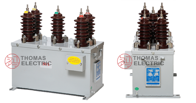
Product Show

Working Principle
Operating on Faraday’s law of electromagnetic induction, the combined transformer integrates separate voltage and current transformation sections within a single weatherproof enclosure. The voltage transformer section employs open-core construction with epoxy resin cast primary and secondary windings, transforming line voltage to standardized 100 V output. The current transformer section features toroidal magnetic cores with primary conductor passing through the aperture and secondary windings wound around the core, delivering standardized 5 A secondary current proportional to primary current. Both sections provide galvanic isolation and accurate signal representation for three-phase three-wire metering systems.
System Application Position
- Outdoor Distribution Networks: 10 kV overhead line and pole-mounted distribution systems
- High-Voltage Metering: Revenue-grade electricity measurement at distribution voltage levels
- Urban and Rural Grids: Energy metering boxes for residential and commercial feeders
- Industrial Substations: Load monitoring and power quality measurement in factory distribution systems
- Grid Modernization: Smart grid integration and advanced metering infrastructure (AMI) applications
Structural Overview
Epoxy resin cast construction for both VT and CT sections ensures superior insulation performance, moisture resistance, and mechanical strength suitable for outdoor service. The fully-enclosed metal cabinet provides IP-rated protection against environmental ingress while maintaining excellent thermal dissipation. Compact three-phase V/V configuration reduces installation footprint and simplifies feeder metering arrangements in space-constrained outdoor installations.
Model Designation

Model Code Explanation
- J — Combined instrument transformer (VT + CT integrated assembly)
- L — Current transformer section designation
- S — Three-phase configuration (three-wire system)
- Z — Cast-resin (epoxy) insulated structure
- W — Outdoor service rating
- 10 — Voltage class (kV)
Service Conditions
The JLSZW-10 series combined instrument transformers are designed for outdoor operation under normal service conditions in medium-voltage distribution systems.
- Installation environment: Outdoor installation with protection from direct weather exposure
- Altitude: ≤ 1000 m (higher altitude shall be specified for engineering confirmation)
- Ambient temperature: −25 °C to +40 °C
- Relative humidity: Daily average ≤ 95%, monthly average ≤ 90%
- Environmental conditions: Suitable for outdoor use; resistant to moisture, dust, and pollution; withstands normal mechanical shock and vibration in distribution environments
- Pollution severity: Suitable for moderate pollution environments (site-specific assessment required for heavy industrial areas)
Construction
Construction Design
- Overall structure: Integrated three-phase combined assembly in weatherproof metal enclosure
- VT section insulation: Epoxy resin cast construction with open magnetic core design
- CT section insulation: Epoxy resin cast construction with toroidal closed magnetic core (high-quality cold-rolled silicon steel)
- Enclosure: Fully sealed metal cabinet with IP protection rating suitable for outdoor service
- Configuration: V/V connection scheme (two voltage transformers + two current transformers) for three-phase three-wire systems
- Terminals: Outdoor-rated primary and secondary terminal arrangements with weather sealing
The epoxy resin casting provides stable insulation properties and resistance to moisture, contamination, UV radiation, and aging for long-term outdoor service. The metal enclosure ensures electromagnetic shielding and mechanical protection.
Windings & Terminal Marking

Voltage Transformer Terminals:
- Primary terminals (per VT unit): A-X or B-Y designation per phase assignment
- Secondary terminals (per VT unit): a-x or b-y designation per phase assignment
Current Transformer Terminals:
- Primary terminals (per CT unit): P1 / P2 designation per phase assignment
- Secondary terminals (per CT unit): 1S1 / 1S2 designation per metering core
Terminal markings follow standard instrument transformer polarity conventions. Correct terminal identification and phase sequence shall be observed to ensure accurate metering and protection performance in three-phase systems.
Technical Data
This section provides selection-oriented technical data for the JLSZW-10 series outdoor combined instrument transformer used in 10 kV class AC systems (50 Hz). Data shown below is intended for preliminary selection of voltage and current transformation ratios, accuracy classes, and rated burdens.
Definitions: Voltage transformer ratio specifies primary-to-secondary voltage transformation. Current transformer ratio specifies primary-to-secondary current transformation. Accuracy class indicates measurement precision per applicable standard. Rated output (VA) is specified per secondary core. Ith is the rated short-time thermal current (1 s) for CT section. Idyn is the rated dynamic current (peak) for CT section.
Data Reference
Voltage Transformer Section Data
| Model | Rated Voltage Ratio (V) |
Accuracy Class |
Rated Output (VA) |
Maximum Output (VA) |
Insulation Level (kV) |
|---|---|---|---|---|---|
| JLSZW-6/10 | 3000/100 | 0.2 / 0.5 | 15 / 30 | 300 | 3.6/25/40 |
| JLSZW-6/10 | 6000/100 | 0.2 / 0.5 | 15 / 30 | 300 | 7.2/32/60 |
| JLSZW-6/10 | 10000/100 | 0.2 / 0.5 | 15 / 30 | 300 | 12/42/75 |
Current Transformer Section Data
| Model | Rated Current Ratio (A) |
Accuracy Class |
Rated Output (VA) |
Thermal Stability Current (kA) |
Dynamic Stability Current (kA) |
Insulation Level (kV) |
|---|---|---|---|---|---|---|
| JLSZW-6/10 | 5~200/5 | 0.2S | 10 | 100 I₁n | 2.5 I₁th | 12/42/75 |
| JLSZW-6/10 | 5~200/5 | 0.2 | 10 | 100 I₁n | 2.5 I₁th | 12/42/75 |
Standards & Normative References
| Standard | Title | Application |
|---|---|---|
| GB/T 20840.4-2015 | Instrument Transformers – Part 4: Combined Instrument Transformers | Primary standard for combined VT+CT assemblies |
| GB/T 20840.1 | Instrument Transformers – Part 1: General Requirements | General requirements for both VT and CT sections |
| GB/T 20840.2 | Instrument Transformers – Part 2: Current Transformers | CT section-specific requirements |
| GB/T 20840.3 | Instrument Transformers – Part 3: Voltage Transformers | VT section-specific requirements |
| IEC 61869-1 | Instrument Transformers – Part 1: General Requirements | International reference standard (alignment) |
| IEC 61869-2 | Instrument Transformers – Part 2: Additional Requirements for Current Transformers | International CT requirements (reference) |
| IEC 61869-3 | Instrument Transformers – Part 3: Additional Requirements for Inductive Voltage Transformers | International VT requirements (reference) |
Factory Test Compliance
- Routine tests per applicable GB/IEC requirements (including polarity/marking verification, ratio verification, and accuracy verification per specified class and burden for both VT and CT sections)
- Dielectric tests per insulation coordination requirements and applicable standard (separate testing for VT and CT sections)
- Partial discharge test where specified by the project requirement
- Visual and dimensional inspection including marking, workmanship conformity, and enclosure integrity
- Type and special tests as required by the project specification (environmental testing, IP rating verification, thermal cycling)
Installation & Dimensions
Outline

The JSZW-6kV combined transformer adopts a 10kV “V/V” wiring mode, supporting three-phase three-line two-component systems.

- Outline dimensions and mounting details are provided in the dimensional drawings and installation manual.
- The combined transformer shall be securely mounted using the designated fixing arrangement suitable for outdoor pole or wall mounting.
- Primary connections shall be made via outdoor-rated terminals with appropriate weather sealing and creepage distances.
- Secondary wiring shall be routed through dedicated cable glands with proper sealing against moisture ingress.
- Adequate clearance shall be maintained for insulation coordination, heat dissipation, and maintenance access.
- Grounding connection shall be established per local electrical safety requirements.
Note: JLSZW-6kV uses 10 kV V/V connection configuration, suitable for three-phase three-wire two-element metering systems.
Ordering Information
When placing an order, the required configuration shall be specified according to the local grid requirements, applicable standards, and project technical specification. The following parameters shall be clearly stated for technical confirmation and production release:
- Voltage transformer ratio (e.g., 10000/100 V)
- Current transformer ratio (e.g., 100/5 A)
- Voltage transformer accuracy requirements (e.g., 0.2 / 0.5 class)
- Current transformer accuracy requirements (e.g., 0.2S class)
- Voltage transformer rated burden (VA) for each secondary core
- Current transformer rated burden (VA) for each secondary core
- Connection scheme (standard V/V or other if specified)
- Enclosure protection rating (IP rating if special requirement)
- Environmental conditions (temperature range, altitude, pollution level if non-standard)
If local utility or project requirements apply (e.g., special insulation level, enhanced pollution resistance, specific terminal arrangement, documentation language, or required certificates), specify them at the ordering stage. Special configurations shall be confirmed by technical agreement and final data sheet prior to production.