Product Overview
Functional Definition
The JLSZW-35 combined instrument transformer is an integrated three-phase outdoor measurement device incorporating both voltage transformation and current transformation functions in a single cast-resin insulated assembly. This combined unit provides galvanically isolated secondary voltage and current signals for energy metering, protection relay operation, and instrumentation applications in 35 kV class AC power distribution systems.
Key Ratings
| Item | Specification (per order / nameplate) |
|---|---|
| System voltage class | 35 kV class (outdoor substation and distribution applications) |
| Rated frequency | 50 Hz (60 Hz available upon request) |
| VT configuration | Two single-phase VTs in V/V connection (measuring three-phase voltages) |
| CT configuration | Two current transformers in series connection on A-phase and C-phase |
| VT rated voltage ratio | 35000/100 V (nominal) |
| VT accuracy classes | 0.2 / 0.5 for metering cores |
| VT rated output | 30 VA (0.2 class) / 50 VA (0.5 class) |
| CT rated current ratio | 5~200/5 A (ratio adjustable via taps) |
| CT accuracy classes | 0.2S / 0.2 for metering and protection cores |
| CT rated output | 10 VA per core as specified |
| CT short-circuit withstand | Ith = 100×I1n (1 s); Idyn = 2.5×Ith (peak) |
| Insulation level (all windings) | Um = 42 kV / AC withstand = 95 kV / Lightning impulse = 195 kV |
| Applicable standards | IEC 61869-1 / IEC 61869-2 / IEC 61869-3; GB/T 20840 series |
| Environmental protection | Outdoor type, IP54 sealed enclosure; no oil, eco-friendly cast resin |
Product Shows

JDZW-35 fully-enclosed epoxy resin voltage transformer

LZZW-35 Epoxy Resin Cast Current Transformer

Working Principle
The JLSZW-35 integrates two voltage transformers and two current transformers within a single outdoor-rated epoxy resin enclosure. The voltage transformer section employs electromagnetic induction with iron cores and secondary windings to step down primary voltage to standardized 100 V output. The current transformer section features toroidal magnetic cores with primary conductors passing through the apertures; primary current induces proportional flux, delivering standardized 5 A secondary current through connected burden. The V/V voltage connection measures all three phase voltages using only two single-phase VT units. Current measurement on A-phase and C-phase enables three-phase power calculation and overcurrent protection.
System Application Position
- Outdoor Substations: 35 kV outdoor switchgear installations and ring main units
- Energy Metering: Revenue-grade three-phase power and energy measurement systems
- Protection Circuits: Overvoltage, undervoltage, overcurrent, and earth fault protection relays
- Distribution Monitoring: SCADA systems, load monitoring, and power quality measurement
- Replacement Projects: Eco-friendly substitute for oil-immersed combined instrument transformers
Structural Overview
Outdoor-rated epoxy resin cast construction with fully-enclosed weatherproof design ensures superior insulation performance, UV resistance, moisture protection, and pollution resistance. The pole-mounted or platform-mounted configuration provides space-efficient installation in outdoor substations while maintaining excellent electrical clearances and mechanical strength under environmental stress.
Model Designation

Model Code Explanation
- J — Instrument transformer (general designation)
- L — Current transformer function included
- S — Three-phase configuration (三相)
- Z — Pillar/post type mounting structure
- W — Outdoor service (户外)
- 35 — Voltage class (kV)
Configuration Details
The JLSZW-35 combined instrument transformer integrates voltage and current measurement functions:
- Voltage Section: Two single-phase voltage transformers connected in V/V configuration, providing three-phase voltage measurement from two units
- Current Section: Two window-type current transformers installed in series on A-phase and C-phase primary conductors
- Integration: All components mounted within a single outdoor-rated epoxy resin enclosure for space efficiency and reduced installation complexity
Service Conditions
The JLSZW-35 combined instrument transformer is designed for outdoor operation under specified environmental conditions in medium-voltage power distribution systems.
- Installation environment: Outdoor installation (protected from direct exposure to severe precipitation where applicable)
- Altitude: Not exceeding 2000 m above sea level (higher altitude shall be specified for engineering confirmation and insulation coordination adjustment)
- Ambient temperature: −40 °C to +40 °C
- Relative humidity: Daily average ≤ 95%, monthly average ≤ 90% (condensation conditions accounted for in design)
- Environmental conditions: Outdoor pollution environment per IEC 60815 classification (pollution severity level to be specified); no explosive or flammable atmosphere; mechanical shock and vibration per applicable standard
- UV exposure: Epoxy resin formulation includes UV stabilizers for long-term outdoor service
Construction
Construction Design
- Structure: Post (pillar) type for outdoor platform or pole mounting
- Insulation: Fully enclosed vacuum-cast epoxy resin insulation system (outdoor-rated formulation)
- VT Core: Silicon steel laminated cores with secondary windings; V/V connection topology
- CT Core: Ring-type (window-type) magnetic cores with adjustable ratio taps
- Enclosure: Weather-sealed epoxy resin housing with IP54 protection rating; UV-resistant surface treatment
- Terminals: Outdoor-rated terminal blocks with tracking-resistant barriers and sealing glands
The outdoor epoxy resin casting provides stable insulation properties and resistance to moisture, UV radiation, thermal cycling, contamination, and aging for long-term outdoor service without oil maintenance.
Windings & Terminal Marking

Voltage Transformer Terminals:
- Primary terminals (VT1): A-X (U1-U2)
- Primary terminals (VT2): C-X (W1-W2)
- Secondary terminals (VT1): a-x (u1-u2)
- Secondary terminals (VT2): c-x (w1-w2)
Current Transformer Terminals:
- Primary terminals (CT on A-phase): P1-P2
- Primary terminals (CT on C-phase): P1-P2
- Secondary terminals (CT A-phase, Core 1): 1S1-1S2
- Secondary terminals (CT C-phase, Core 1): 1S1-1S2
Terminal markings follow standard VT and CT polarity conventions per IEC 61869. Correct terminal identification and polarity verification shall be observed to ensure metering accuracy and protection relay performance.
Technical Data
This section provides selection-oriented technical data for the JLSZW-35 three-phase outdoor epoxy resin combined instrument transformer used in 35 kV class AC systems (50 Hz). Data shown below is intended for preliminary selection of voltage ratio, current ratio, accuracy class combinations, rated outputs, and short-circuit withstand capability.
Definitions: VT accuracy class indicates metering precision for voltage measurement. CT accuracy class combination indicates available metering/protection cores. Rated output (VA) is specified per secondary core. Ith is the rated short-time thermal current for CT (typically 1 s). Idyn is the rated dynamic current (peak) for CT.
Notation: VT and CT specifications are independent within the combined unit. Customer shall specify VT ratio, VT accuracy, VT burden, CT ratio, CT accuracy, and CT burden according to project metering and protection requirements.
VT Technical Parameters
| Model | Rated Voltage Ratio (V) |
Accuracy Class |
Rated Output (VA) |
Limit Output (VA) |
Rated Insulation Level (kV) |
|---|---|---|---|---|---|
| JLSZW-35 | 35000/100 | 0.2 | 30 | 500 | 42/95/195 |
| JLSZW-35 | 35000/100 | 0.5 | 50 | 500 | 42/95/195 |
CT Technical Parameters
| Model | Current Ratio (A) |
Accuracy Class |
Rated Output (VA) |
Thermal Stability Current (kA) |
Dynamic Stability Current (kA) |
Rated Insulation Level (kV) |
|---|---|---|---|---|---|---|
| JLSZW-35 | 5~200/5 | 0.2S | 10 | 100×I1n | 2.5×Ith | 42/95/195 |
| JLSZW-35 | 5~200/5 | 0.2 | 10 | 100×I1n | 2.5×Ith | 42/95/195 |
Standards & Normative References
| Standard | Title | Application |
|---|---|---|
| IEC 61869-1 | Instrument Transformers – Part 1: General Requirements | General requirements for VT and CT |
| IEC 61869-2 | Instrument Transformers – Part 2: Additional Requirements for Current Transformers | CT-specific requirements |
| IEC 61869-3 | Instrument Transformers – Part 3: Additional Requirements for Inductive Voltage Transformers | VT-specific requirements |
| GB/T 20840.1 | Instrument Transformers – Part 1: General Requirements | National standard (aligned with IEC 61869 framework) |
| GB/T 20840.2 | Instrument Transformers – Part 2: Current Transformers | National CT requirements |
| GB/T 20840.3 | Instrument Transformers – Part 3: Inductive Voltage Transformers | National VT requirements |
| IEC 60815 | Selection and Dimensioning of High-Voltage Insulators for Polluted Conditions | Outdoor insulation design under pollution |
| IEC 60068-2-1 | Environmental Testing – Cold | Low temperature performance verification |
| IEC 60068-2-2 | Environmental Testing – Dry Heat | High temperature performance verification |
Factory Test Compliance
- Routine tests (VT) per IEC 61869-3 / GB/T 20840.3 (including polarity/marking, ratio verification, accuracy verification per specified class and burden, and dielectric tests)
- Routine tests (CT) per IEC 61869-2 / GB/T 20840.2 (including polarity/marking, ratio verification, accuracy verification per specified class and burden, and dielectric tests)
- Dielectric tests per insulation coordination requirements: AC withstand voltage test, lightning impulse withstand test
- Partial discharge test where specified by project requirement or per applicable standard
- Visual and dimensional inspection including marking, terminal arrangement, and workmanship conformity
- Type and special tests as required by project specification (including thermal stability, dynamic stability, outdoor environmental tests)
Installation & Dimensions
- Outline dimensions and mounting details are provided in the dimensional drawings.
- The combined transformer shall be securely mounted using the designated fixing base or mounting bracket on outdoor platform or pole structure.
- Primary busbar connections shall be made through the designated primary terminals for both VT and CT sections with appropriate torque specification.
- Adequate clearance shall be maintained for insulation coordination, heat dissipation, and maintenance access per applicable outdoor installation standard.
- Grounding connections shall be provided on the metallic mounting base and secondary neutral points per local electrical safety code.
Outlines
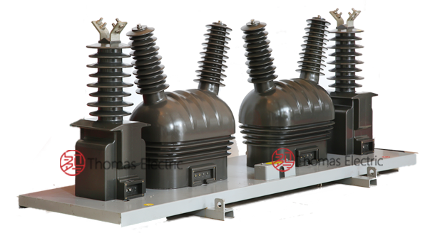
JLSZW-35 Outdoor Combined Instrument Transformer

Safety Notes
- VT secondary circuits shall be protected with appropriate fuses to prevent secondary short-circuit damage.
- CT secondary circuit must never be left open when the transformer is energized, as dangerous high voltage may appear across the secondary terminals.
- During inspection or maintenance, all secondary circuits shall be short-circuited and grounded before disconnecting any instruments or relays.
- One point of each VT secondary circuit and each CT secondary circuit should be reliably grounded in accordance with applicable standards.
- All installation, operation, and maintenance work shall comply with local electrical safety regulations for outdoor high-voltage equipment.
- Observe proper clearances and approach distances per applicable outdoor substation safety standards.
Ordering Information
When placing an order, the required configuration shall be specified according to the local grid requirements, applicable standards, and project technical specification. The following parameters shall be clearly stated for technical confirmation and production release:
VT Selection: Determine rated primary voltage from system nominal voltage (e.g., 35 kV system). Select accuracy class based on metering requirements (0.2 for revenue metering, 0.5 for indication). Confirm rated burden (VA) from sum of connected meters, transducers, relays, and wiring losses.
CT Selection: Determine rated primary current from feeder/load rating and expected operating range. Select accuracy class 0.2S for revenue metering or 0.2 for general metering. Confirm rated burden (VA) for each secondary circuit based on connected instruments and wiring losses. Verify short-circuit withstand capability (Ith/Idyn) against system prospective fault current.
If local utility or project requirements apply (e.g., special insulation level, ice/snow loading, seismic rating, terminal arrangement, mounting constraints, documentation language, or required certificates), specify them at the ordering stage. Special configurations and non-standard ratings shall be confirmed by technical agreement and final data sheet prior to production.