Product Overview
Functional Definition
The JLSZW series outdoor epoxy resin cast combined instrument transformers, also referred to as energy metering boxes, are precision electromagnetic instruments designed for integrated voltage measurement, current measurement, energy metering, and relay protection in medium to high-voltage AC power systems. These combined units utilize electromagnetic induction principles to provide galvanically isolated secondary signals for both voltage and current, suitable for rated voltages of 10kV to 35kV and frequency of 50Hz in three-phase systems.
Key Ratings
| Item | Specification (per order / nameplate) |
|---|---|
| System voltage class | 10kV / 12kV / 35kV class (outdoor substation and distribution applications) |
| Rated frequency | 50 Hz (60 Hz available upon request) |
| Configuration type | Combined VT + CT unit (voltage transformer + current transformer) |
| VT connection | V/V connection (two single-phase VTs); upgradable to Y/Y three-phase |
| CT configuration | Two CTs on A-phase and C-phase with adjustable ratio taps |
| Rated secondary current (CT) | 1 A or 5 A (adjustable via taps) |
| Accuracy classes | VT and CT cores as specified (e.g., 0.2 / 0.5 for metering; 10P for protection) |
| Rated burden | Per core/winding as specified (VA) |
| Built-in metering | Active and reactive energy meters integrated |
| Insulation structure | Epoxy resin cast, fully sealed, pillar-type structure |
| Lightning protection | Zinc oxide surge arrester required within 1 m installation radius |
| Applicable standards | GB20840.4-2015 (combined transformers); GB20840.2-2014 / GB20840.1-2010 (CT); GB20840.3-2013 / GB20840.1-2010 (VT) |
| Application environment | Outdoor substations, industrial power distribution, urban and rural electrical networks |
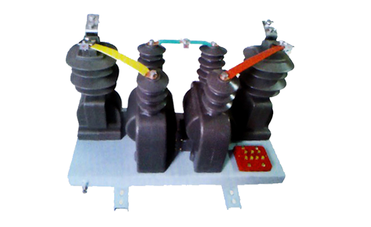
Product Shows

Working Principle
The JLSZW combined instrument transformer integrates voltage and current measurement in a single outdoor-rated enclosure. The voltage transformer section operates on electromagnetic induction with two single-phase VTs configured in V/V connection, transforming primary high voltage to standardized secondary voltage (typically 100V or 100/√3V). The current transformer section features two ring-type core CTs positioned on A-phase and C-phase primary conductors, delivering secondary current signals proportional to primary load current. Both VT and CT secondary outputs feed integrated energy meters for active and reactive power measurement, while also supporting relay protection and SCADA interfacing.
System Application Position
- Outdoor Substations: Urban and rural 10kV-35kV outdoor distribution substations
- Industrial Power Distribution: Factory electrical systems, petrochemical plants, mining operations
- Energy Metering: Revenue-grade electricity measurement with integrated active/reactive meters
- Protection Circuits: Overcurrent, overvoltage, and comprehensive protection schemes
- Grid Monitoring: SCADA integration and remote monitoring applications
Structural Overview
Epoxy resin cast construction with fully sealed, pillar-type outdoor design ensures superior insulation performance, UV resistance, weatherability, and long-term operational stability with minimal maintenance requirements. The integrated structure combines voltage transformers and current transformers in a compact enclosure, reducing installation footprint and simplifying field wiring. Advanced epoxy casting technology provides excellent resistance to arc tracking, aging, and environmental contamination for extended service life in harsh outdoor conditions.
Model Designation

Model Code Explanation
- J — Combined instrument transformer (VT + CT integrated unit)
- L — Current transformer component
- S — Three-phase configuration
- Z — Outdoor support (pillar) type structure
- W — Outdoor application / weatherproof enclosure
- 6 / 10 / 35 — Voltage class (kV): 6kV, 10kV, or 35kV systems
Configuration Variants
The JLSZW series supports two primary connection configurations:
- V/V Connection (Standard): Two single-phase voltage transformers in V/V arrangement with two current transformers on A-phase and C-phase, suitable for three-phase three-wire systems (two-element metering)
- Y/Y Connection (Upgrade Option): Three single-phase voltage transformers in Y/Y arrangement with current transformers on all three phases, enabling three-phase four-wire metering and enhanced measurement accuracy
Service Conditions
The JLSZW series combined instrument transformers are designed for outdoor operation under normal service conditions in medium to high-voltage power distribution systems.
- Installation environment: Outdoor installation in substations and distribution networks
- Altitude: Not exceeding 1000 m above sea level (higher altitude configurations require engineering confirmation and derating)
- Ambient temperature: −25 °C to +40 °C (extended range options available)
- Relative humidity: Daily average ≤ 95%, monthly average ≤ 90% (condensation and frost conditions anticipated in outdoor service)
- Pollution severity: Up to pollution level III per IEC 60815 (higher pollution levels require special configuration)
- Environmental conditions: Outdoor exposure to rain, snow, ice, solar radiation, and atmospheric contamination; designed to withstand typical outdoor environmental stresses
- Seismic resistance: Designed for seismic intensity VII (customization available for higher seismic zones)
- Wind load: Suitable for typical regional wind loading conditions
Construction
Construction Design
- Structure: Outdoor pillar-type, fully sealed epoxy resin cast enclosure
- VT Insulation: Epoxy resin cast voltage transformers with full insulation level
- CT Insulation: Epoxy resin cast current transformers integrated in the same structure
- Core Configuration: Ring-type magnetic cores for current transformers; laminated cores for voltage transformers
- Terminal Arrangement: Weatherproof secondary terminal compartment with sealed cable entries
- Integrated Meters: Built-in active and reactive energy meters in protected enclosure
- Environmental Protection: UV-resistant epoxy formulation with anti-tracking surface treatment
The epoxy resin casting technology provides stable insulation properties, excellent resistance to moisture, contamination, UV radiation, and aging, ensuring reliable long-term outdoor service with minimal maintenance requirements. The fully sealed construction prevents ingress of moisture, dust, and pollutants, maintaining consistent dielectric performance throughout the service life.
Windings & Terminal Marking
Voltage Transformer Terminals:
- Primary terminals (A-phase VT): A / a
- Primary terminals (C-phase VT): C / c
- Secondary terminals (A-phase VT): a1 / a2 / aO
- Secondary terminals (C-phase VT): c1 / c2 / cO
Current Transformer Terminals:
- Primary terminals (A-phase CT): P1(A) / P2(A)
- Primary terminals (C-phase CT): P1(C) / P2(C)
- Secondary terminals (A-phase CT, metering core): 1S1(A) / 1S2(A)
- Secondary terminals (A-phase CT, protection core): 2S1(A) / 2S2(A)
- Secondary terminals (C-phase CT, metering core): 1S1(C) / 1S2(C)
- Secondary terminals (C-phase CT, protection core): 2S1(C) / 2S2(C)
Terminal markings follow standard VT and CT polarity conventions per GB and IEC standards. Correct terminal identification and polarity must be observed to ensure accurate metering, proper protection operation, and safe installation. One point of each secondary circuit shall be reliably grounded per applicable standards.
Technical Data
This section provides selection-oriented technical data for the JLSZW series outdoor epoxy resin cast combined instrument transformers used in 10kV to 35kV class AC systems (50 Hz). Data shown below is intended for preliminary configuration selection based on voltage class, metering accuracy requirements, protection functions, and system integration needs.
Definitions: VT ratio is the voltage transformation ratio (e.g., 10000/100V). CT ratio is the current transformation ratio with adjustable taps. Accuracy class indicates metering and/or protection core performance. Rated burden is specified per secondary core (VA). Built-in meters indicate integrated active/reactive energy measurement capability.
(PT Section)
| Voltage Class |
VT Primary Voltage |
VT Secondary Voltage |
Accuracy Class |
Rated Burden (VA) |
Insulation Level |
|---|---|---|---|---|---|
| 6 kV / 10 kV | 6000V / 10000V | 100V or 100/√3V | 0.2 / 0.5 | 50-200 VA | Per GB20840.3-2013 |
| 12 kV | 12000V | 100V or 100/√3V | 0.2 / 0.5 | 50-200 VA | Per GB20840.3-2013 |
| 35 kV | 35000V | 100V or 100/√3V | 0.2 / 0.5 | 50-200 VA | Per GB20840.3-2013 |
(CT Section)
| Rated Primary Current (A) |
CT Ratio (adjustable) |
Accuracy Class (Metering / Protection) |
Rated Burden (VA) |
Ith (1s) | Idyn (peak) |
|---|---|---|---|---|---|
| 5-600 A | Various ratios with tap adjustment | 0.2S / 10P10 | 5-30 VA per core | 20-60 kA | 50-150 kA |
| 10-800 A | Various ratios with tap adjustment | 0.5 / 10P15 | 5-30 VA per core | 20-75 kA | 50-187.5 kA |
Integrated Energy Metering Configuration
| Meter Type | Measurement
Function |
Accuracy
Class |
Communication |
|---|---|---|---|
| Active Energy Meter | Active power (kWh) measurement | Class 0.5S or 1.0 | RS485 / Modbus (optional) |
| Reactive Energy Meter | Reactive power (kvarh) measurement | Class 2.0 | RS485 / Modbus (optional) |
Standards & Normative References
| Standard | Title | Application |
|---|---|---|
| GB20840.4-2015 | Instrument Transformers – Part 4: Combined Transformers | Combined transformer general requirements |
| GB/T 20840.1-2010 | Instrument Transformers – Part 1: General Requirements | General requirements for both VT and CT |
| GB/T 20840.2-2014 | Instrument Transformers – Part 2: Current Transformers | CT-specific requirements |
| GB20840.3-2013 | Instrument Transformers – Part 3: Voltage Transformers | VT-specific requirements |
| IEC 61869-1 | Instrument Transformers – Part 1: General Requirements | International general requirements |
| IEC 61869-2 | Instrument Transformers – Part 2: Additional Requirements for Current Transformers | International CT requirements |
| IEC 61869-3 | Instrument Transformers – Part 3: Additional Requirements for Voltage Transformers | International VT requirements |
| IEC 60815 | Selection and Dimensioning of High-Voltage Insulators for Polluted Conditions | Outdoor insulation design for pollution |
| DL/T 866 | Technical Specifications for Combined Instrument Transformers | National grid technical requirements |
Factory Testing Compliance
- Routine tests per GB20840 series and IEC 61869 series requirements (including ratio verification, polarity verification, accuracy tests for both VT and CT cores at specified burdens)
- Dielectric tests including power frequency withstand voltage, lightning impulse withstand, and partial discharge tests per insulation coordination requirements
- Temperature rise test for continuous rated operation and overload conditions
- Energy meter accuracy verification for integrated active and reactive meters
- Environmental tests including UV aging, rain/moisture resistance, and pollution performance (where specified)
- Visual and dimensional inspection including marking verification, workmanship conformity, and installation interface checks
- Type tests and special tests as required by project specification or applicable standards
Installation & Dimensions
Outline


- Outline dimensions and mounting details are provided in product-specific dimensional drawings and installation manuals.
- The combined transformer shall be securely mounted on a concrete foundation or steel structure using the designated fixing holes and anchor bolts.
- Primary high-voltage connections are made via overhead line terminals or busbar interfaces depending on system configuration.
- Secondary terminals are accessed through weatherproof terminal compartment with cable gland entries.
- Adequate clearance shall be maintained for phase-to-phase, phase-to-ground insulation, personnel safety, heat dissipation, and maintenance access per applicable standards.
- Zinc oxide surge arresters must be installed within 1 meter of primary terminals for effective lightning protection coordination.
Typical Installation Configuration (JLSZW-6kV / 10kV)
The JLSZW-6kV and JLSZW-10kV models utilize V/V connection with three-phase three-wire, two-element metering configuration. The compact outdoor pillar-type structure integrates voltage transformers, current transformers, and energy meters in a single weatherproof enclosure suitable for pole-mounted or pad-mounted installation in outdoor substations.
Safety
- VT secondary fuses or circuit breakers shall be provided for each secondary circuit to prevent overload and enable safe disconnection.
- CT secondary circuit must never be left open when the transformer is energized, as dangerous high voltage may appear across the secondary terminals causing equipment damage and personnel hazard.
- During inspection or maintenance, CT secondary circuit shall be short-circuited before disconnecting any instruments or meters.
- One point of each VT and CT secondary circuit shall be reliably grounded in accordance with GB and IEC standards to prevent secondary overvoltage and ensure personnel safety.
- Periodic inspection of integrated energy meters, terminal connections, surge arrester status, and external insulation condition is recommended per maintenance schedule.
- All installation, commissioning, and maintenance work shall comply with local electrical safety regulations, utility requirements, and manufacturer instructions.
Ordering Information
When placing an order, the required configuration shall be specified according to local grid requirements, applicable standards, and project technical specification. The following parameters shall be clearly stated for technical confirmation and production release:
- Voltage class (6kV / 10kV / 12kV / 35kV)
- VT primary voltage and secondary voltage (e.g., 10000V / 100V)
- VT accuracy class and rated burden (e.g., 0.2 class, 100 VA)
- CT rated primary current range and transformation ratio (including tap adjustment requirements)
- CT rated secondary current (1 A or 5 A)
- CT accuracy requirements (metering and/or protection accuracy class combination, e.g., 0.2S / 10P10)
- CT rated burden (VA) for each secondary core/winding
- CT short-circuit withstand requirements: Ith (1 s) and Idyn (peak)
- Connection configuration: V/V (standard two-element) or Y/Y (three-element upgrade)
- Integrated meter requirements: Active/reactive meter specifications, accuracy class, communication interface
- Environmental conditions: Altitude, ambient temperature range, pollution level, seismic zone
- Lightning protection coordination: Surge arrester specifications and installation requirements
If local utility or project requirements apply (e.g., specific insulation levels, partial discharge limits, pollution severity, seismic resistance, terminal arrangement, mounting configuration, documentation language, or required certificates), specify them at the ordering stage. Custom configurations shall be confirmed by technical agreement and final data sheet prior to production.