Product Overview
Functional Definition
The JLSZW3-6 and JLSZW3-10 series outdoor dry-type combined instrument transformers are integrated electromagnetic measurement devices that combine voltage transformer (VT) and current transformer (CT) functions in a single sealed enclosure. These transformers provide simultaneous voltage and current measurement for three-phase AC power systems rated at 50 Hz, with system voltage classes of 6 kV and 10 kV. The combined configuration delivers galvanically isolated secondary signals for energy metering, protection relaying, and supervisory control applications in urban/rural grids, outdoor substations, and industrial distribution networks.
Key Ratings
| Item | Specification (per order / nameplate) |
|---|---|
| System voltage class | 6 kV / 10 kV class (outdoor distribution applications) |
| Rated frequency | 50 Hz (60 Hz available upon request) |
| VT voltage ratios | 3000/100 V, 6000/100 V, 10000/100 V |
| VT accuracy classes | 0.2 / 0.5 |
| VT rated output | 15 VA / 30 VA per core |
| VT limit output | 300 VA |
| CT current ratios | 5~200/5 A |
| CT accuracy classes | 0.2S / 0.2 |
| CT rated output | 10 VA per core |
| CT short-circuit withstand | Ith: 100 × I₁n (1 s), Idyn: 2.5 × Ith (peak) |
| VT insulation level (JLSZW3-6) | 7.2/32/60 kV |
| VT insulation level (JLSZW3-10) | 12/42/75 kV |
| CT insulation level | 12/42/75 kV |
| Connection configuration | Three-phase four-wire Y/Yo |
| Applicable standards | GB 20840.4-2015 (Combined); GB 20840.2-2014, GB 20840.1-2010 (CT); GB 20840.3-2013, GB 20840.1-2010 (VT) |
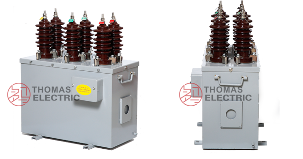
Product Shows
 Thomas Electric")
Working Principle
The combined transformer integrates independent voltage and current measurement functions using electromagnetic induction principles. The voltage transformer section employs a wound-core configuration with primary windings connected to the power system and secondary windings delivering standardized 100 V output. The current transformer section utilizes toroidal cores with primary conductors passing through apertures and secondary windings providing 5 A output current proportional to primary current. Both VT and CT sections operate simultaneously to supply complete three-phase voltage and current signals for metering instruments, protective relays, and monitoring systems.
System Application Position
- Outdoor Distribution Networks: 6-10 kV overhead lines and pole-mounted switchgear
- Energy Metering Stations: Revenue-grade three-phase electricity measurement and billing
- Protection Systems: Overcurrent, overvoltage, and directional protection schemes
- Substation Monitoring: Remote terminal units (RTU) and SCADA data acquisition
- Industrial Power Systems: Factory distribution panels and outdoor transformer stations
Structural Overview
The combined transformer features fully-enclosed metal housing with integrated epoxy resin cast VT and CT components. The voltage transformer sections use exposed iron cores with high-quality cold-rolled grain-oriented silicon steel, with primary and secondary windings wound on core limbs. Current transformer sections employ closed iron cores with premium silicon steel, ensuring measurement accuracy and stability. Three voltage transformers and three current transformers are assembled in a sealed metal enclosure, providing compact installation footprint, environmental protection, and reliable long-term operation in outdoor conditions.
Model Designation
 Thomas Electric")
Code Explanation
- J — Voltage transformer (VT/PT)
- L — Current transformer (CT)
- S — Three-phase configuration
- Z — Cast-resin (epoxy) insulated structure
- W — Outdoor installation type
- 3 — Design series code
- 6 / 10 — Voltage class (kV)
Description
JLSZW3-6 and JLSZW3-10 designate the system voltage class (6 kV or 10 kV). The combined transformer integrates three single-phase voltage transformers and three single-phase current transformers in Y/Yo three-phase four-wire connection. The specific voltage ratio, current ratio, accuracy classes, and rated burdens are defined by project specification and confirmed on the nameplate.
Service Conditions
The JLSZW3 series combined transformers are designed for outdoor operation under normal service conditions in medium-voltage distribution systems.
- Installation environment: Outdoor installation in sheltered or exposed locations
- Altitude: Not exceeding 1000 m above sea level (higher altitude applications require engineering confirmation)
- Ambient temperature: −25 °C to +40 °C
- Relative humidity: Daily average ≤ 95%, monthly average ≤ 90% (at +20 °C reference)
- Environmental conditions: Free from severe salt fog, industrial contamination, or explosive atmospheres; no abnormal vibration or mechanical shock
- Lightning protection: Zinc oxide surge arrester required within 1 meter of installation point
Construction
Construction Design
Voltage Transformer Section:
- Core type: Wound core with exposed structure
- Core material: High-quality cold-rolled grain-oriented silicon steel sheets
- Insulation: Epoxy resin cast construction
- Windings: Primary and secondary coils wound on core limbs
Current Transformer Section:
- Core type: Closed ring-type iron core
- Core material: Premium quality silicon steel laminations
- Insulation: Epoxy resin monolithic casting
- Configuration: Pass-through primary with secondary windings on toroidal core
Enclosure Assembly:
- Housing: Sealed metal cabinet with environmental protection
- Components: Three VT units + three CT units in integrated assembly
- Terminals: Primary and secondary terminal blocks accessible via compartment doors
- Protection rating: Weather-resistant construction for outdoor service
The epoxy resin casting provides stable insulation properties, moisture resistance, pollution resistance, and aging resistance for reliable outdoor operation. The fully-enclosed metal housing protects components from environmental exposure while maintaining electrical clearances and creepage distances.
Terminal Arrangement & Marking
 Thomas Electric")
Voltage Transformer Terminals:
- Primary terminals (per phase): A / B / C / N (neutral)
- Secondary terminals (per phase): a / b / c / n (neutral)
- Connection: Y/Yo three-phase four-wire configuration
Current Transformer Terminals:
- Primary terminals (per phase): P1 / P2
- Secondary terminals (Phase A): 1K1 / 1L1
- Secondary terminals (Phase B): 1K2 / 1L2
- Secondary terminals (Phase C): 1K3 / 1L3
Terminal markings follow standard polarity conventions per GB 20840 series. Correct terminal identification is essential for accurate metering and proper protection relay operation. Wiring diagrams and terminal assignment are provided with each unit.
Technical Data
Voltage Transformer Specifications
| Model | Rated Voltage Ratio (V) |
Accuracy Class |
Rated Output (VA) |
Limit Output (VA) |
Rated Insulation Level (kV) |
|---|---|---|---|---|---|
| JLSZW3-6 | 3000/100 | 0.2 / 0.5 | 15 / 30 | 300 | 3.6/25/40 |
| 6000/100 | 7.2/32/60 | ||||
| — | — | ||||
| JLSZW3-10 | 3000/100 | 0.2 / 0.5 | 15 / 30 | 300 | 3.6/25/40 |
| 6000/100 | 7.2/32/60 | ||||
| 10000/100 | 12/42/75 |
Voltage Transformer Notes:
- Accuracy class 0.2 for precision metering; 0.5 for general metering applications
- Rated output (burden) available as 15 VA or 30 VA per secondary winding
- Limit output capacity: 300 VA continuous
- Insulation level format: Um/ACSD/LI (system voltage / short-duration power-frequency / lightning impulse)
- Secondary voltage: 100 V line-to-neutral (57.7 V phase-to-neutral in Y connection)
Current Transformer Specifications
| Model | Rated Current Ratio (A) |
Accuracy Class |
Rated Output (VA) |
Rated Short-Time Thermal Current (kA) |
Rated Dynamic Stability Current (kA peak) |
Rated Insulation Level (kV) |
|---|---|---|---|---|---|---|
| JLSZW3-6 | 5~200/5 | 0.2S | 10 | 100 × I₁n | 2.5 × Ith | 12/42/75 |
| 0.2 | ||||||
| JLSZW3-10 | 5~200/5 | 0.2S | 10 | 100 × I₁n | 2.5 × Ith | 12/42/75 |
| 0.2 |
Current Transformer Notes:
- Accuracy class 0.2S for electronic energy meters (extended range); 0.2 for standard metering
- Rated primary current (I₁n) selectable from 5 A to 200 A in standard steps
- Rated secondary current: 5 A (1 A available as special order)
- Short-time thermal current (Ith): 100 times rated primary current for 1 second
- Dynamic stability current (Idyn): 2.5 times Ith (peak value)
- Burden power factor: cosφ = 0.8 (inductive) unless otherwise specified
Accuracy and Burden
Voltage Transformer Accuracy Performance:
Voltage transformers meet accuracy class 0.2 or 0.5 requirements per GB 20840.3-2013 at rated burden from 25% to 100% of rated voltage. Ratio error and phase displacement remain within specified limits across the operating range.
Current Transformer Accuracy Performance:
Current transformers meet accuracy class 0.2S or 0.2 requirements per GB 20840.2-2014. Class 0.2S provides extended accuracy range from 1% to 120% of rated primary current, suitable for electronic energy meters. Accuracy limits are maintained at rated burden and rated frequency.
Burden Selection:
VT rated burden (15 VA or 30 VA) shall accommodate total connected load including meters, relays, and wiring resistance. CT rated burden (10 VA) shall cover secondary circuit impedance at rated current (5 A). Actual burden should be verified during system design to ensure accuracy compliance.
Standards Compliance
Applicable Standards
- GB 20840.4-2015: Instrument transformers – Part 4: Additional requirements for combined transformers
- GB 20840.2-2014: Instrument transformers – Part 2: Additional requirements for current transformers
- GB 20840.1-2010: Instrument transformers – Part 1: General requirements
- GB 20840.3-2013: Instrument transformers – Part 3: Additional requirements for inductive voltage transformers
- IEC 61869 series: Instrument transformers (reference standard)
Testing and Acceptance
Each combined transformer unit undergoes factory testing per applicable standards:
- Routine tests: Voltage ratio, current ratio, polarity, accuracy, burden, insulation resistance, dielectric withstand
- Insulation test: Power-frequency voltage withstand test on primary and secondary circuits
- Lightning impulse test: Full-wave impulse voltage test per insulation level specification
- Short-circuit withstand test: Verification of Ith and Idyn ratings (type test or calculation)
- Visual and dimensional inspection: Nameplate data, terminal marking, workmanship verification
- Special tests: Partial discharge measurement, temperature rise test (where specified)
Installation & Dimensions
Installation Guidelines
- Combined transformer shall be mounted on stable foundation or pole-mounted bracket with secure mechanical fixing
- Mounting position shall provide adequate clearance for electrical safety, heat dissipation, and maintenance access
- Primary connections made via busbar or cable termination as specified by project design
- Secondary circuits routed through cable glands with proper sealing and strain relief
- Surge arrester installation mandatory within 1 meter of primary terminals per GB requirements
- Grounding connection required on designated terminal following local electrical codes
Outlines
JLSZW3-6kV / 10kV Combined Transformer
 Thomas Electric")
Note: Dimensional drawings show typical configuration. Actual dimensions confirmed on approved drawings prior to manufacture. Mounting hole patterns and terminal locations may vary by specification.
Safety Notes
- VT secondary circuit should not be short-circuited during operation; miniature circuit breaker or fuse protection recommended
- CT secondary circuit must never be open when primary carries current; dangerous high voltage will appear at secondary terminals
- During inspection or maintenance, CT secondary shall be short-circuited before disconnecting any instruments or wiring
- One point of VT secondary neutral and one point of CT secondary circuit shall be reliably grounded per applicable standards
- All installation and maintenance operations shall comply with national and local electrical safety regulations
- De-energize primary circuit and verify absence of voltage before accessing terminal compartments
Ordering Information
When placing an order, the required configuration shall be specified according to local utility requirements, applicable standards, and project technical specification. The following parameters shall be clearly stated for technical confirmation and production release:
Voltage Transformer Requirements:
- Rated primary voltage / voltage ratio: 3000/100 V, 6000/100 V, or 10000/100 V
- Accuracy class: 0.2 or 0.5
- Rated burden: 15 VA or 30 VA per secondary winding
- Insulation level: Per system voltage class and project specification
Current Transformer Requirements:
- Rated primary current / transformation ratio: 5/5 A through 200/5 A in standard steps
- Accuracy class: 0.2S or 0.2
- Rated burden: 10 VA per secondary winding
- Short-circuit withstand: Ith (1 s) and Idyn (peak) per system fault level
System and Configuration:
- System voltage class: 6 kV or 10 kV
- Rated frequency: 50 Hz (specify if 60 Hz required)
- Connection type: Three-phase four-wire Y/Yo (standard)
- Installation type: Outdoor pole-mounted or foundation-mounted
If special requirements apply (non-standard ratios, additional accuracy cores, special terminal arrangements, mounting configurations, documentation language, certificates, or factory testing beyond routine), specify them at ordering stage for technical review and confirmation. Custom configurations require engineering approval and final datasheet before production release.