Product Overview
The JLSZY-10, JLSZY-6 epoxy resin cast combined transformers are three-phase integrated measurement solutions designed for accurate energy metering and protection in medium-voltage outdoor power distribution systems. These combined units integrate three single-phase fully-insulated voltage transformers in Y/Yo configuration with current transformers embedded in A-phase and C-phase, providing simultaneous voltage and current transformation in a compact, oil-free design.
Key Ratings
| Item | Specification (per order / nameplate) |
|---|---|
| System voltage class | 6 kV / 10 kV class (outdoor distribution applications) |
| Rated frequency | 50 Hz (60 Hz available upon request) |
| Rated secondary current (CT portion) | 5 A, 2 A, or 1 A (adjustable via taps) |
| Rated secondary voltage (VT portion) | 100 V (three-phase) |
| Accuracy classes (VT) | 0.2 class: 3 × 15 VA; 0.5 class: 3 × 30 VA |
| CT short-circuit withstand | Ith (thermal, 1 s) and Idyn (dynamic, peak) as specified per ratio |
| Insulation level | 1.2/42/75 kV (Um/Ud/Up) |
| Minimum creepage distance | 440 mm |
| Applicable standards | IEC 61869-3 / IEC 61869-2 / IEC 61869-1; GB/T 20840.3 / 20840.2 / 20840.1; GB 1207; GB 1208 |
| Model variants | JLSZY-6 / JLSZY-10 |
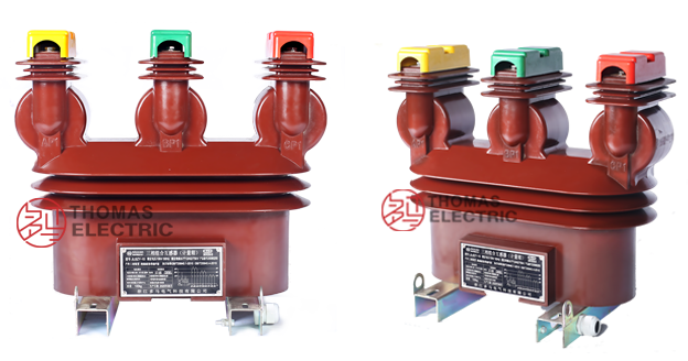
Product Shows

Working Principle
The voltage transformer section operates on electromagnetic induction with three single-phase VT cores in Y/Yo configuration, transforming primary voltage to standardized 100 V secondary output. Current transformers embedded in A-phase and C-phase utilize toroidal magnetic cores with adjustable secondary taps, enabling flexible output current selection (5A/2A/1A) to optimize metering accuracy across varying load conditions. The integrated design eliminates the need for separate VT and CT installations while maintaining galvanic isolation between primary and secondary circuits.
System Application Position
- Medium Voltage Distribution: 6-10 kV outdoor distribution networks and substations
- Energy Metering: Three-phase active and reactive energy measurement systems
- Grid Modernization: Oil-free retrofit projects in urban and rural power grids
- Industrial Metering: Mining, manufacturing, and commercial facility power monitoring
Structural Overview
Dry-type epoxy resin cast construction with fully-enclosed outdoor-rated design provides superior insulation performance, pollution resistance, and maintenance-free operation. The three-phase integrated configuration reduces installation footprint and simplifies field wiring. High-strength weather-resistant epoxy shell ensures long-term outdoor service with minimal maintenance requirements—periodic surface cleaning only.
Model Designation

Model Code Explanation
- J — Combined instrument transformer (VT + CT integrated)
- L — Current transformer portion
- S — Three-phase configuration
- Z — Support (post) type installation
- Y — Voltage transformer (VT) portion included
- 6 / 10 — Voltage class (kV)
Configuration Details
JLSZY-6 and JLSZY-10 are voltage-class variants with identical construction principles. Selection depends on system nominal voltage. Both models feature three single-phase VTs in Y/Yo connection with CTs integrated in A-phase and C-phase. Secondary current output is adjustable via internal taps to match connected metering and protection equipment requirements.
Service Conditions
The JLSZY series combined instrument transformers are designed for outdoor installation under the following service conditions:
- Installation environment: Outdoor installation (weather-resistant enclosure)
- Altitude: Not exceeding 1000 m above sea level (higher altitude applications require engineering confirmation)
- Ambient temperature: −25 °C to +40 °C
- Relative humidity: Daily average ≤ 95%, monthly average ≤ 90%
- Pollution level: Designed for moderate pollution environments with 440 mm minimum creepage distance
- Seismic resistance: Specify seismic requirements at ordering stage for high-risk zones
- Environmental conditions: Free from severe vibration, mechanical shock, explosive or highly corrosive atmospheres
Construction
Construction Design
- Structure: Three-phase combined VT + CT, outdoor post-type mounting
- Insulation: Fully enclosed dry-type epoxy resin cast insulation (oil-free)
- VT configuration: Three single-phase VTs in Y/Yo connection, secondary voltage 100 V
- CT configuration: CTs embedded in A-phase and C-phase with adjustable secondary taps (5A/2A/1A)
- Enclosure: High-strength weather-resistant epoxy resin shell with UV and aging resistance
The epoxy resin casting provides stable insulation properties, excellent pollution resistance, moisture resistance, and long-term outdoor service capability without oil maintenance requirements.
Windings & Terminal Marking

- VT primary terminals (three-phase): A / B / C / N
- VT secondary terminals (three-phase): a / b / c / n
- CT primary: Integrated with VT primary (A-phase and C-phase)
- CT secondary terminals (A-phase): 1K1 / 1K2
- CT secondary terminals (C-phase): 2K1 / 2K2
- CT tap selection: Internal adjustable taps for 5A / 2A / 1A output
Terminal markings follow standard polarity conventions. Correct terminal identification and tap configuration shall be observed to ensure metering accuracy and protection performance.
Technical Data
This section provides selection-oriented technical data for the JLSZY-6/10 three-phase dry-type outdoor combined instrument transformer used in 6 kV and 10 kV class AC systems (50 Hz). Data shown below is intended for preliminary selection of current ratio, accuracy class, rated output, and short-circuit withstand capability.
Definitions: Rated primary current refers to CT nominal input current. Ith is the rated short-time thermal current (1 s). Idyn is the rated dynamic current (peak). Rated secondary output (VA) is specified per VT accuracy class. CT secondary output is specified separately based on connected burden.
Notation: Ith/Idyn may vary by primary current ratio; acceptance shall be based on nameplate values and factory test report.
Data Reference
| Rated Primary Current (A) |
Rated Short-time Thermal Current (kA RMS) |
Rated Dynamic Current (kA peak) |
Rated Secondary Output (VA) |
|---|---|---|---|
| 5-10 | 1.0 | 2.5 | 10 |
| 10-20 | 1.5 | 3.75 | 10 |
| 15-30 | 2.4 | 6.0 | 10 |
| 20-40 | 3.0 | 7.5 | 10 |
| 30-60 | 4.5 | 11 | 10 |
| 40-75 | 8.0 | 20 | 10 |
| 50-100 | 9.0 | 22.5 | 10 |
| 75-150 | 12 | 30 | 10 |
| 100-200 | 16 | 40 | 10 |
| 150-300 | 24 | 60 | 10 |
| 200-400 | 32 | 80 | 10 |
| 300-600 | 60 | 100 | 10 |
| 400-800 | 80 | 100 | 10 |
| 500-1000 | 80 | 100 | 10 |
VT Portion – Technical Parameters
| Accuracy Class |
Rated Output (VA per phase) |
Total Output (Three-Phase) |
|---|---|---|
| 0.2 | 15 VA | 3 × 15 VA |
| 0.5 | 30 VA | 3 × 30 VA |
Insulation Parameters
| Parameter | Value |
|---|---|
| Rated insulation level | 1.2/42/75 kV (Um/Ud/Up) |
| Minimum creepage distance | 440 mm |
| Power frequency withstand voltage (1 min, dry) | 42 kV RMS |
| Lightning impulse withstand voltage (1.2/50 μs) | 75 kV peak |
Standards & Normative References
| Standard | Title | Application |
|---|---|---|
| IEC 61869-1 | Instrument Transformers – Part 1: General Requirements | General requirements for combined transformers |
| IEC 61869-2 | Instrument Transformers – Part 2: Additional Requirements for Current Transformers | CT portion requirements |
| IEC 61869-3 | Instrument Transformers – Part 3: Additional Requirements for Voltage Transformers | VT portion requirements |
| GB/T 20840.1 | Instrument Transformers – Part 1: General Requirements | National standard (aligned with IEC 61869 framework) |
| GB/T 20840.2 | Instrument Transformers – Part 2: Current Transformers | National CT requirements |
| GB/T 20840.3 | Instrument Transformers – Part 3: Voltage Transformers | National VT requirements |
| GB 1208 | Current Transformers | National CT standard where specified |
| GB 1207 | Voltage Transformers | National VT standard where specified |
| IEC 60694 | Common Specifications for High-Voltage Switchgear and Controlgear Standards | Environmental and service condition reference |
| IEC 60085 | Electrical Insulation – Thermal Evaluation | Insulation thermal evaluation reference |
Factory Test Compliance
- Routine tests per applicable IEC/GB requirements including:
- Polarity and terminal marking verification
- VT ratio and accuracy verification per specified class and burden
- CT ratio and accuracy verification per specified class and burden
- Winding resistance measurement
- Dielectric tests per insulation coordination requirements:
- Power frequency withstand test (42 kV, 1 min)
- Lightning impulse withstand test (75 kV peak, 1.2/50 μs)
- Partial discharge test where specified by project requirement
- Temperature rise test (type test, as applicable)
- Visual and dimensional inspection including marking and workmanship conformity
- Type and special tests as required by project specification (seismic, pollution, moisture resistance)
Installation & Dimensions
- Outline dimensions and mounting details are provided in the dimensional drawings.
- The combined transformer shall be securely mounted using designated fixing holes on a stable foundation or structure.
- Primary connection via overhead line or busbar depending on installation configuration.
- Adequate clearance shall be maintained for insulation, heat dissipation, and maintenance access.
- Secondary wiring shall be routed through weatherproof conduit to metering and protection equipment.
Outlines


JLSZY-10 Three-Phase Combined Instrument Transformer
Safety Notes
- CT secondary circuit must never be left open when the transformer is energized, as dangerous high voltage may appear across the secondary terminals.
- VT secondary circuit should be properly fused and protected against overload.
- During inspection or maintenance, CT secondary circuits shall be short-circuited before disconnecting any instruments.
- One point of each secondary circuit (VT and CT) should be reliably grounded in accordance with applicable standards.
- All installation and maintenance work shall comply with local electrical safety regulations and high-voltage work permits.
- Outdoor installations require periodic inspection and surface cleaning to maintain creepage distance and insulation performance.
Ordering Information
When placing an order, the required configuration shall be specified according to the local grid requirements, applicable standards, and project technical specification. The following parameters shall be clearly stated for technical confirmation and production release:
- Model designation: JLSZY-6 or JLSZY-10 (system voltage class)
- CT portion:
- Rated primary current / transformation ratio (A-phase and C-phase)
- Rated secondary current (5 A, 2 A, or 1 A)
- Accuracy class and rated burden (VA)
- Short-circuit withstand requirements: Ith (1 s) and Idyn (peak)
- VT portion:
- Accuracy class (0.2 or 0.5)
- Rated burden (15 VA or 30 VA per phase)
- Environmental specifications:
- Installation altitude (if exceeding 1000 m)
- Pollution level and seismic requirements
- Ambient temperature range (if exceeding standard conditions)
- Customization requirements:
- Enhanced pollution resistance (increased creepage distance)
- Special mounting or terminal arrangements
- Accessory requirements (AC/DC power modules, enhanced enclosure, etc.)