Product Overview
Functional Definition
The JLSZY-35 series combined instrument transformer is a precision outdoor measurement and protection device designed for simultaneous voltage and current measurement in three-phase AC power systems. Operating at the 35 kV voltage class with rated frequency of 50 Hz, this unit integrates voltage transformers (PT) and current transformers (CT) in a single cast epoxy resin enclosure, providing galvanically isolated secondary signals for energy metering, revenue measurement, and relay protection applications in outdoor substations and industrial distribution systems.
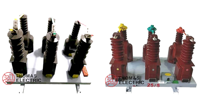
Product Show

Key Ratings
| Item | Specification (per order / nameplate) |
|---|---|
| System voltage class | 35 kV class (outdoor substation and distribution applications) |
| Rated frequency | 50 Hz (60 Hz available upon request) |
| PT rated voltage ratio | 35000/100 V (three-phase system) |
| CT rated current ratio | 5~200/5 A (per specification) |
| PT accuracy classes | 0.2 or 0.5 for metering applications |
| CT accuracy classes | 0.2S or 0.2 for metering applications |
| PT rated burden | 30 VA (class 0.2) or 50 VA (class 0.5) |
| CT rated burden | 10 VA |
| PT limiting output | 500 VA |
| CT short-circuit withstand | Ith: 100×I1n (thermal), Idyn: 2.5×Ith (dynamic) |
| Rated insulation level | 42/95/195 kV (Um/Ud/Up) |
| Applicable standards | GB/T 20840.4-2015 (combined transformers); GB/T 20840.1-2010, 20840.2-2014 (CT); GB/T 20840.1-2010, 20840.3-2013 (PT) |
| PT connection configuration | V/V connection using two single-phase units |
| CT installation positions | Phase A and Phase C (two-element metering) |
Working Principle
Voltage Transformer (PT) Section: Two single-phase fully-insulated voltage transformers connected in V/V configuration provide three-phase voltage measurement. Operating on electromagnetic induction principles, the primary winding exposed to system voltage induces proportional secondary voltage (100 V line-to-neutral) for metering and protection devices.
Current Transformer (CT) Section: Two toroidal current transformers installed on Phase A and Phase C utilize Faraday’s law to convert primary current to standardized 5 A secondary output. The magnetic core with primary conductor passing through the aperture generates flux proportional to primary current, inducing secondary voltage that drives burden-connected instruments.
System Application Position
- 35 kV Outdoor Substations: Urban and rural distribution substations requiring combined voltage and current measurement
- Revenue Metering: Utility-grade three-phase energy measurement for billing and load monitoring
- Industrial Distribution: High-voltage industrial feeders and plant distribution systems
- Grid Monitoring: SCADA integration and supervisory control systems requiring simultaneous V/I measurement
- Relay Protection: Overcurrent, overvoltage, and distance protection schemes
Structural Overview
The JLSZY-35 employs a post-type outdoor design with fully-enclosed epoxy resin cast construction. The integrated housing contains both PT and CT elements in a single mechanical assembly, providing UV resistance, anti-aging properties, and pollution performance suitable for harsh outdoor environments. The maintenance-free design eliminates oil-filled transformer concerns while delivering superior insulation performance and mechanical strength for long-term outdoor service.
Model Designation

Model Code Explanation
- J — Combined instrument transformer
- L — Current element (CT component)
- S — Voltage element (PT component: three-phase)
- Z — Cast-resin (epoxy) insulated structure
- Y — Outdoor (户外) application type
- 35 — Voltage class (kV)
Service Conditions
The JLSZY-35 series combined instrument transformer is designed for outdoor operation under normal service conditions in 35 kV power distribution systems.
- Installation environment: Outdoor installation (pole-mounted or platform-mounted)
- Altitude: Not exceeding 1000 m above sea level (higher altitude shall be specified for engineering confirmation and correction factors applied)
- Ambient temperature: −25 °C to +40 °C (outdoor duty cycle)
- Relative humidity: Daily average ≤ 95%, monthly average ≤ 90% (condensation permissible with outdoor-rated insulation)
- Environmental conditions: Suitable for outdoor exposure including UV radiation, precipitation, and pollution; pollution severity class per IEC 60815 or project specification; free from explosive or corrosive atmospheres
- Earthquake resistance: Seismic intensity ≤ 8 degrees (Chinese seismic code) or per regional requirement
Construction
Construction Design
- Overall structure: Post-type outdoor combined unit
- Enclosure material: Fully-enclosed epoxy resin cast insulation with UV-stabilized formulation
- PT configuration: Two single-phase voltage transformers in V/V connection (fully-insulated type)
- CT configuration: Two ring-type current transformers on Phase A and Phase C
- Secondary terminals: Weather-sealed terminal compartment with clearly marked connections
- Mounting: Base-mounted with fixing holes for concrete foundation or steel structure
The epoxy resin casting provides stable dielectric properties, resistance to moisture ingress, UV degradation, and surface contamination, ensuring reliable long-term outdoor service. The maintenance-free construction eliminates oil handling and environmental risks associated with traditional liquid-filled transformers.
Windings & Terminal Marking

Voltage Transformer Terminals:
- Primary terminals (PT): A, B, C (phase connections); N (neutral, if applicable)
- Secondary terminals (PT): a, b, c (line-to-neutral 100 V outputs); n (neutral point)
Current Transformer Terminals:
- Primary terminals (CT): P1 / P2 (Phase A); P1 / P2 (Phase C)
- Secondary terminals (CT, Phase A): 1S1 / 1S2
- Secondary terminals (CT, Phase C): 2S1 / 2S2
Terminal markings follow standard polarity conventions per GB/T 20840 series. Correct terminal identification and polarity observation are essential for accurate metering and protection operation. CT secondary taps (where provided) enable ratio adjustment in the field.
Technical Data
This section provides selection-oriented technical data for the JLSZY-35 outdoor three-phase combined instrument transformer used in 35 kV class AC systems (50 Hz). Data shown below is intended for preliminary selection of voltage and current transformation ratios, accuracy classes, rated burdens, and insulation coordination.
Definitions: PT rated voltage ratio is the primary-to-secondary voltage transformation for the voltage element. CT rated current ratio is the primary-to-secondary current transformation for the current element. Rated burden (VA) is specified per secondary output. Ith is the rated short-time thermal current. Idyn is the rated dynamic current (peak). Insulation level is expressed as Um/Ud/Up (maximum system voltage / power-frequency withstand / lightning impulse withstand).
Data Reference
Voltage Transformer Technical Data
| Model | Rated Voltage Ratio (V) |
Accuracy Class |
Rated Output (VA) |
Limiting Output (VA) |
Rated Insulation Level (kV) |
|---|---|---|---|---|---|
| JLSZY-35 | 35000/100 | 0.2 | 30 | 500 | 42/95/195 |
| JLSZY-35 | 35000/100 | 0.5 | 50 | 500 | 42/95/195 |
Current Transformer Technical Data
| Model | Rated Current Ratio (A) |
Accuracy Class |
Rated Output (VA) |
Thermal Stability Current (Ith) |
Dynamic Stability Current (Idyn) |
Rated Insulation Level (kV) |
|---|---|---|---|---|---|---|
| JLSZY-35 | 5~200/5 | 0.2S | 10 | 100 × I1n (1 s) | 2.5 × Ith | 42/95/195 |
| JLSZY-35 | 5~200/5 | 0.2 | 10 | 100 × I1n (1 s) | 2.5 × Ith | 42/95/195 |
Standards & Normative References
| Standard | Title | Application |
|---|---|---|
| GB/T 20840.4-2015 | Instrument Transformers – Part 4: Combined Transformers | Primary combined transformer requirements |
| GB/T 20840.1-2010 | Instrument Transformers – Part 1: General Requirements | General requirements for both PT and CT elements |
| GB/T 20840.2-2014 | Instrument Transformers – Part 2: Additional Requirements for Current Transformers | CT element requirements |
| GB/T 20840.3-2013 | Instrument Transformers – Part 3: Additional Requirements for Voltage Transformers | PT element requirements |
| IEC 61869-1 | Instrument Transformers – Part 1: General Requirements | International reference standard |
| IEC 61869-2 | Instrument Transformers – Part 2: Additional Requirements for Current Transformers | International CT reference |
| IEC 61869-3 | Instrument Transformers – Part 3: Additional Requirements for Voltage Transformers | International PT reference |
| IEC 60815 | Selection and Dimensioning of High-Voltage Insulators for Polluted Conditions | Outdoor pollution performance reference |
Factory Test Compliance
- Routine tests per applicable GB/IEC requirements including:
- PT and CT polarity and terminal marking verification
- Voltage ratio and current ratio verification
- Accuracy verification at specified burdens and classes
- Dielectric withstand tests (power frequency and impulse)
- Visual and dimensional inspection including marking clarity and workmanship conformity
- Partial discharge test where specified by project requirement
- Type and special tests as required by project specification (temperature rise, short-circuit withstand, etc.)
Installation & Dimensions
- Outline dimensions and mounting details are provided in the dimensional drawings supplied with each order.
- The transformer shall be securely mounted on a concrete foundation or steel platform using the designated fixing holes.
- Primary HV connections shall be made via outdoor connectors or bushings suitable for 35 kV service.
- Secondary terminal compartment shall be weather-sealed with appropriate cable glands for outgoing secondary circuits.
- Adequate clearance shall be maintained for electrical safety, heat dissipation, and maintenance access per outdoor substation design standards.
- Lightning protection: Zinc oxide surge arrester shall be installed within 1 meter of the transformer as specified.
Outlines

Safety Notes
- CT secondary handling: CT secondary circuit must never be left open when the transformer is energized, as dangerous high voltage may appear across the secondary terminals. During inspection or maintenance, short-circuit the CT secondary before disconnecting any instruments.
- PT secondary protection: PT secondary circuits shall be protected by appropriate fuses rated for the burden and cable configuration.
- Grounding: One point of each CT secondary circuit and the PT secondary neutral shall be reliably grounded in accordance with GB/T 20840 and local electrical codes.
- Outdoor installation: Ensure proper sealing of all secondary terminal compartments to prevent moisture ingress.
- Lightning protection: Verify surge arrester installation and grounding system integrity before energization.
- Personnel safety: All installation and maintenance work shall comply with local electrical safety regulations and outdoor substation safety procedures.
Ordering Information
When placing an order, the required configuration shall be specified according to the grid requirements, applicable standards, and project technical specification. The following parameters shall be clearly stated for technical confirmation and production release:
- Determine PT voltage ratio based on system nominal voltage (typically 35000/100 V for 35 kV systems).
- Determine CT primary current (Ip) based on feeder/load rating and expected operating range.
- Select PT and CT accuracy requirements (e.g., 0.2 or 0.2S for revenue metering; 0.5 for general measurement).
- Confirm rated burden (VA) for PT and CT secondary circuits based on connected devices and cable losses.
- Verify CT short-circuit withstand capability (Ith/Idyn) against the system fault level.
- Specify environmental conditions (altitude, temperature, pollution) if outside normal service conditions.
Special configurations (non-standard ratios, additional accuracy cores, custom mounting, specific insulation levels, or documentation requirements) shall be confirmed by technical agreement and final datasheet prior to production.