Product Overview
The JSZF-3/6/10kV series voltage transformers are precision electromagnetic instruments designed for accurate voltage measurement, energy metering, and relay protection applications in medium-voltage AC power systems. These transformers utilize electromagnetic induction principles to provide galvanically isolated secondary voltage signals proportional to primary voltage.
The JSZF series is constructed with durable epoxy resin insulation, providing superior electrical performance and mechanical strength for rated voltages of 3kV, 6kV, and 10kV systems. The compact semi-enclosed design enhances installation convenience while improving operational safety and service efficiency. Compliant with relevant standards, the JSZF series is suitable for substations, industrial facilities, and other medium-voltage distribution applications, delivering reliable measurement accuracy and operational reliability.
Key Ratings
| Item | Specification (per order / nameplate) |
|---|---|
| System voltage class | 3kV / 6kV / 10kV class (indoor medium-voltage distribution applications) |
| Rated frequency | 50 Hz (60 Hz available upon request) |
| Rated secondary voltage | 100/√3 V or 100 V per configuration |
| Accuracy classes | Metering and/or protection cores as specified (e.g., 0.2, 0.5, 1, 3, 6P) |
| Rated burden | Per core/winding as specified (VA) |
| Burden power factor | cosφ = 0.8 (lagging) unless otherwise specified by the project standard |
| Maximum output capacity | 1000 VA (sustained capacity under specific conditions) |
| Insulation level | Per applicable standard and project specification |
| Applicable standards | IEC 61869-1 / IEC 61869-3; GB/T 20840.1 / GB/T 20840.3-2013 |
| Model variants | JSZF-3 / JSZF-6 / JSZF-10 |
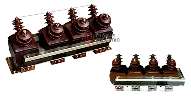
Product Show

Working Principle
Operating on Faraday’s law of electromagnetic induction, the voltage transformer features a magnetic core with primary and secondary windings. The magnetic flux generated by primary voltage induces proportional voltage in the secondary winding, delivering standardized voltage output through connected burden. The galvanic isolation ensures safe signal transmission for measurement and protection systems.
System Application Position
- Medium Voltage Distribution: 3-10kV switchgear and distribution panels
- Energy Metering: Revenue-grade electricity measurement systems
- Protection Circuits: Overvoltage, undervoltage, and ground fault protection schemes
- SCADA Integration: Supervisory control and data acquisition systems
Structural Overview
Epoxy resin cast construction with semi-enclosed design ensures superior insulation performance, moisture resistance, and mechanical strength. The compact mounting configuration provides efficient installation in medium-voltage switchgear environments while maintaining excellent electrical clearance and creepage distances. The semi-enclosed structure balances environmental protection with accessibility for inspection and maintenance.
Model Designation

Model Code Explanation
- J — Voltage transformer (VT)
- S — Three-phase / Single-phase configuration
- Z — Cast epoxy resin insulated structure
- F — Semi-enclosed design
- 3 / 6 / 10 — Voltage class (kV)
Service Conditions
The JSZF-3/6/10 series voltage transformers are designed for indoor operation under normal service conditions in medium-voltage power systems.
- Installation environment: Indoor installation only (recommended for vertical mounting to optimize performance)
- Altitude: Not exceeding 1000 m above sea level (higher altitude configurations available upon request)
- Ambient temperature: −5 °C to +40 °C
- Relative humidity: ≤95%, no condensation
- Pollution degree: Suitable for light to moderate pollution environments
- Environmental conditions: Free from corrosive gases or vapors; free from explosive or flammable media; no severe vibration or mechanical shock
Construction
Construction Design
- Structure: Semi-enclosed type for indoor switchgear
- Insulation: Epoxy resin cast insulation system
- Core: Magnetic core design with optimized flux distribution
- System: Integrated primary and secondary insulation system
The epoxy resin casting provides stable insulation properties and resistance to moisture, contamination, and aging for long-term indoor service. The semi-enclosed structure combines protective enclosure with accessibility for maintenance and inspection.
Structural Configuration Details
JSZF-3 and JSZF-6 models integrate three-phase three-pole structure with single-phase two-pole structure. In the three-phase section, the N terminal is not grounded. In the single-phase section, after series connection, the O terminal must be grounded during fault conditions to coordinate with system ground fault protection devices, preventing equipment damage and ensuring normal operation. The design is simplified and reliable, suitable for measurement and protection tasks in medium-voltage distribution systems.
Windings & Terminal Marking
- Primary terminals: Phase-specific marking per nameplate
- Secondary terminals: Standard secondary terminal marking per IEC/GB conventions
Terminal markings follow standard VT polarity conventions. Under normal operating conditions, correct terminal identification shall be observed to ensure metering and protection performance. The O terminal grounding requirement for JSZF-3 and JSZF-6 single-phase sections must be strictly followed during fault conditions.
Technical Data
This section provides selection-oriented technical data for the JSZF-3/6/10 series indoor, epoxy resin cast voltage transformers used in 3kV, 6kV, and 10kV class AC systems (50 Hz). Data shown below is intended for preliminary selection of accuracy class combinations and rated burdens.
Key Parameters:
- Creepage distance: Meets Class II pollution degree requirements
- Burden power factor: cosφ = 0.8 (lagging)
- Applicable standards: GB/T 20840.3-2013 and GB/T 20840.1-2010
- Customization support: JSZF-3, JSZF-6, and JSZF-10 can be customized for high-precision versions or special parameters based on application requirements
- Single-ratio operation: Each JSZF unit supports only single voltage ratio operation; multi-ratio simultaneous operation is not recommended
Data Reference
| Model | Rated Voltage Ratio (V) |
0.2 Class (VA) |
0.5 Class (VA) |
1 Class (VA) |
3 Class (VA) |
6P Class
(VA) |
Max Output (VA) |
Insulation Level (kV) |
|---|---|---|---|---|---|---|---|---|
| JSZF-3 | 3000/√3 / 100/√3 / 100/3 | 60 | 150 | 300 | 450 | 50 | 1000 | 3.6/25/40 |
| JSZF-6 | 6000/√3 / 100/√3 / 100/3 | 60 | 150 | 300 | 450 | 50 | 1000 | 7.2/32/60 |
| JSZF-10 | 10000/√3 / 100/√3 / 100/3 | 75 | 150 | 300 | 450 | 50 | 1000 | 12/42/75 |
Standards & Normative References
| Standard | Title | Application |
|---|---|---|
| IEC 61869-1 | Instrument Transformers – Part 1: General Requirements | General requirements |
| IEC 61869-3 | Instrument Transformers – Part 3: Additional Requirements for Voltage Transformers | VT-specific requirements |
| GB/T 20840.1 | Instrument Transformers – Part 1: General Requirements | National standard (aligned with IEC 61869 framework) |
| GB/T 20840.3-2013 | Instrument Transformers – Part 3: Voltage Transformers | National VT requirements (aligned with IEC 61869-3) |
Factory Test Compliance
- Routine tests per applicable IEC/GB requirements (including polarity/marking, ratio verification, and accuracy verification per specified class and burden)
- Dielectric tests per insulation coordination requirements and applicable standard
- Visual and dimensional inspection including marking and workmanship conformity
- Type and special tests as required by the project specification
Installation
Wiring for JSZF-10

Outline Dimensions

- Outline dimensions and mounting details are provided in the dimensional drawings.
- The transformer shall be securely mounted using the designated fixing holes.
- Primary conductor connections shall be made per the wiring diagram and nameplate instructions.
- Adequate clearance shall be maintained for insulation, heat dissipation, and maintenance access.
Safety Notes
- Secondary circuit fuses must be properly rated and installed to prevent overcurrent damage.
- During inspection or maintenance, the primary circuit shall be de-energized and proper lockout/tagout procedures followed.
- One point of the secondary circuit should be reliably grounded in accordance with applicable standards.
- For JSZF-3 and JSZF-6 models, the O terminal grounding requirement must be strictly followed during fault conditions to coordinate with ground fault protection systems.
- All installation and maintenance work shall comply with local electrical safety regulations.
Ordering Information
When placing an order, the required configuration shall be specified according to the local grid requirements, applicable standards, and project technical specification. The following parameters shall be clearly stated for technical confirmation and production release:
- Model designation (JSZF-3, JSZF-6, or JSZF-10)
- Rated voltage ratio (primary/secondary voltage)
- Application and accuracy requirements (metering and/or protection accuracy class combination)
- Rated burden (VA) for each secondary core/winding
If local utility or project requirements apply (e.g., specific insulation level, terminal arrangement, mounting constraints, documentation language, or required certificates), specify them at the ordering stage. Special configurations shall be confirmed by technical agreement and final data sheet prior to production.
Customization Support
This documentation presents the JSZF-3, JSZF-6, and JSZF-10 voltage transformers’ structure, parameters, and application scenarios. For non-standard models, custom voltage ratios, or special insulation requirements, please contact our technical team for customized solutions. Customization options include voltage ratio, accuracy class, output capacity, insulation level, and mounting configuration modifications to meet specific project requirements.