Product Overview
Functional Definition
The JSZV series (JSZV1-10R, JSZV2-10R, JSZV3-10R) voltage transformers are precision electromagnetic instruments designed for voltage measurement, energy metering, and relay protection applications in medium-voltage AC power systems. These transformers utilize epoxy resin cast insulation with integrated high-voltage fuse protection, providing galvanically isolated secondary voltage signals proportional to primary voltage for metering instruments and protection devices.
Key Ratings
| Item | Specification (per order / nameplate) |
|---|---|
| System voltage class | 3 kV / 6 kV / 10 kV (indoor switchgear and distribution applications) |
| Rated frequency | 50 Hz (60 Hz available upon request) |
| Rated secondary voltage | 100 V, 110 V, or 220 V (line-to-neutral output) |
| Accuracy classes | 0.2, 0.5 for metering; 3P for protection (as specified) |
| Rated output (burden) | Per winding as specified: 75 VA, 120 VA, etc. |
| Insulation level | 12/42/75 kV (Um/AC withstand/LI withstand) |
| Integrated HV fuse | XRNP□-12, rated current 0.2 A, breaking capacity 50 kA |
| Applicable standards | IEC 61869-3; GB/T 20840.3-2013; GB/T 20840.1-2010; IEC 186; GB 1207-2006 |
| Model variants | JSZV1-10R (single-phase) / JSZV2-10R (V-V connection) / JSZV3-10R (three-phase) |
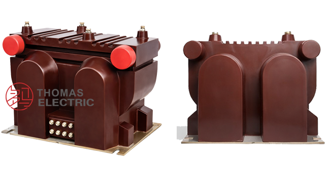
Product Shows
 Thomas Electric")
Working Principle
Operating on Faraday’s law of electromagnetic induction, the voltage transformer features a magnetic core with primary winding connected to the high-voltage system and secondary windings delivering proportional low-voltage output. The integrated high-voltage fuse provides overcurrent protection for the primary winding. Secondary output voltage (100 V, 110 V, or 220 V) is suitable for connection to metering instruments, protection relays, and monitoring equipment.
System Application Position
- Medium Voltage Distribution: 3–10 kV switchgear and distribution panels
- Energy Metering: Revenue-grade electricity measurement systems
- Protection Circuits: Overvoltage, undervoltage, and directional protection schemes
- SCADA Integration: Supervisory control and data acquisition systems
- Industrial Applications: Substations, factories, and commercial power systems
Structural Overview
Epoxy resin cast construction with fully-enclosed design ensures superior insulation performance, moisture resistance, and mechanical strength. The compact configuration provides space-efficient installation in indoor switchgear environments while maintaining excellent electrical clearance and creepage distances. Integrated HV fuse simplifies maintenance and enhances operational safety.
Model Designation
 Thomas Electric")
Model Code Explanation
- J — Voltage transformer (VT / PT)
- S — Three-phase configuration
- Z — Cast-resin (epoxy) insulated, fully enclosed structure
- V — V-V connection type (where applicable)
- 1/2/3 — Phase configuration code: 1 = single-phase; 2 = two-element; 3 = three-phase
- 10 — Voltage class (kV)
- R — Integrated fuse protection (with HV fuse)
Variant Differences
JSZV1-10R, JSZV2-10R, and JSZV3-10R differ in phase configuration and connection type. JSZV1-10R is single-phase for line-to-ground measurement; JSZV2-10R uses V-V connection for three-phase systems with two VT elements; JSZV3-10R provides complete three-phase measurement with three VT elements. Selection depends on measurement requirements and system configuration.
Service Conditions
The JSZV series voltage transformers are designed for indoor operation under normal service conditions in medium-voltage power systems.
- Installation environment: Indoor installation only
- Altitude: Not exceeding 1000 m above sea level (higher altitude shall be specified for engineering confirmation)
- Ambient temperature: −5 °C to +40 °C
- Relative humidity: ≤ 95%, non-condensing
- Pollution degree: II
- Mounting orientation: Vertical installation
- Environmental conditions: Free from corrosive gases or vapors; free from explosive or flammable media; no severe vibration, mechanical shock, or impact
Construction
Construction Design
- Structure: Fully enclosed epoxy resin cast design for indoor switchgear
- Insulation: Vacuum-cast epoxy resin insulation system
- Core: High-permeability silicon steel magnetic core
- HV fuse: Integrated primary winding fuse protection (XRNP□-12)
- System: Combined primary and secondary insulation structure
The epoxy resin casting provides stable insulation properties and resistance to moisture, contamination, and aging for long-term indoor service. Integrated fuse protection enhances safety and simplifies maintenance procedures.
Windings & Terminal Marking
- Primary terminals: A / X (high-voltage side)
- Secondary terminals (Winding 1): a / x (metering output)
- Secondary terminals (Winding 2): Additional winding for protection (if specified)
Terminal markings follow standard VT polarity conventions. Correct terminal identification shall be observed to ensure metering and protection performance. Secondary circuit grounding shall comply with applicable standards.
Technical Data
This section provides selection-oriented technical data for the JSZV-10R series indoor, cast-resin voltage transformer used in 3–10 kV class AC systems (50 Hz / 60 Hz). Data shown below is intended for preliminary selection of accuracy class combinations, rated burdens, and voltage ratios.
Data Reference
| Parameter | Specification |
|---|---|
| Rated primary voltage | 3 kV, 6 kV, 10 kV (line-to-ground: 10/√3 kV) |
| Rated secondary voltage | 100 V, 110 V, 220 V (or 100/√3 V, 110/√3 V) |
| Typical voltage ratio | 10000/√3 : 100/√3 : 100/√3 (example) |
| Rated frequency | 50 Hz (60 Hz upon request) |
| Accuracy class (metering) | 0.2, 0.5 |
| Accuracy class (protection) | 3P |
| Rated output (burden) | 75 VA, 120 VA (per winding, as specified) |
Insulation & Dielectric Data
| Parameter | Specification |
|---|---|
| Highest voltage for equipment (Um) | 12 kV |
| Power frequency withstand voltage (1 min) | 42 kV |
| Lightning impulse withstand voltage (1.2/50 μs) | 75 kV |
| Partial discharge level | Per GB/T 20840 requirements |
Integrated HV Fuse Data
| Parameter | Specification |
|---|---|
| Fuse model | XRNP□-12 |
| Rated current | 0.2 A |
| Breaking capacity | 50 kA |
| Rated voltage | 12 kV |
Standards & Normative References
| Standard | Title | Application |
|---|---|---|
| IEC 61869-1 | Instrument Transformers – Part 1: General Requirements | General requirements |
| IEC 61869-3 | Instrument Transformers – Part 3: Additional Requirements for Inductive Voltage Transformers | VT-specific requirements |
| IEC 186 | Voltage Transformers | Legacy VT standard reference |
| GB/T 20840.1-2010 | Instrument Transformers – Part 1: General Requirements | National standard (aligned with IEC 61869 framework) |
| GB/T 20840.3-2013 | Instrument Transformers – Part 3: Inductive Voltage Transformers | National VT requirements (aligned with IEC 61869-3) |
| GB 1207-2006 | Voltage Transformers | National VT standard where specified by the project |
Factory Test Compliance
- Routine tests per applicable IEC/GB requirements (including polarity/marking, ratio verification, and accuracy verification per specified class and burden)
- Dielectric tests per insulation coordination requirements and applicable standard
- Partial discharge test where specified by the project requirement
- Visual and dimensional inspection including marking and workmanship conformity
- Type and special tests as required by the project specification
The wiring diagram illustrates standard terminal connections for primary and secondary circuits. Observe polarity markings and grounding requirements per applicable standards.
Installation & Dimensions
- Outline dimensions and mounting details are provided in the dimensional drawings.
- The transformer shall be securely mounted using the designated fixing holes.
- Adequate clearance shall be maintained for insulation, heat dissipation, and maintenance access.
- Vertical mounting orientation required for proper operation.
Outline Drawing
 Thomas Electric")
Wiring Diagram
 Thomas Electric")
Safety Notes
- Primary circuit must be de-energized before any inspection, maintenance, or fuse replacement.
- Secondary circuit shall have one point reliably grounded in accordance with applicable standards.
- Do not exceed rated burden capacity to maintain accuracy performance.
- All installation and maintenance work shall comply with local electrical safety regulations.
Ordering Information
When placing an order, the required configuration shall be specified according to the local grid requirements, applicable standards, and project technical specification. The following parameters shall be clearly stated for technical confirmation and production release:
- Model designation (JSZV1-10R / JSZV2-10R / JSZV3-10R)
- Rated primary voltage / voltage ratio (e.g., 10000/√3 : 100/√3 : 100/√3)
- Rated secondary voltage (100 V, 110 V, or 220 V)
- Accuracy class (0.2, 0.5 for metering; 3P for protection)
- Rated output (burden) for each secondary winding (VA)
- Insulation level (12/42/75 kV standard or special requirement)
- Operating environment (temperature, humidity, altitude, pollution degree)
How to Select
- Determine rated primary voltage based on system voltage class (3 kV, 6 kV, or 10 kV).
- Select phase configuration: JSZV1-10R (single-phase), JSZV2-10R (V-V), or JSZV3-10R (three-phase).
- Specify accuracy class for metering (0.2 or 0.5) and/or protection (3P) applications.
- Confirm rated burden (VA) for each secondary winding based on connected instruments and wiring losses.
- Verify insulation level against system requirements.
If local utility or project requirements apply (e.g., special insulation level, partial discharge limit, terminal arrangement, mounting constraints, documentation language, or required certificates), specify them at the ordering stage. Special configurations shall be confirmed by technical agreement and final data sheet prior to production.