Product Overview
Functional Definition
The JSZV12-10R series combined voltage transformers are precision electromagnetic instruments designed for accurate voltage measurement, energy metering, and auxiliary power supply in medium-voltage AC power systems. These combined transformers integrate voltage transformation with built-in high-voltage fuse protection on each phase, utilizing electromagnetic induction principles to provide galvanically isolated secondary voltage signals proportional to primary voltage.
Key Ratings
| Item | Specification (per order / nameplate) |
|---|---|
| System voltage class | 10 kV class (indoor switchgear and distribution applications) |
| Rated frequency | 50 Hz (60 Hz available upon request) |
| Rated voltage ratio | 10000/100 V (metering) or 10/0.1/0.22 kV (dual output with auxiliary power) |
| Secondary voltage outputs | 100 V (precision metering) and 220 V (auxiliary power / control circuit supply) |
| Accuracy classes | 0.2 and 0.5 as specified |
| Rated burden | 20 VA (0.2 class), 60 VA (0.5 class), per ordered specification |
| Maximum output | 500-600 VA (short-time) |
| Insulation level | 12/42/75 kV (Um/Ud/Up) |
| Configuration | Three-phase V-connection (two single-phase units) with integrated fuses on A, B, C phases |
| Fuse protection | Integrated high-voltage fuses on primary windings (A/B/C phases) with accessible secondary terminals for maintenance |
| Applicable standards | GB/T 20840.3-2013, GB/T 20840.4-2015, GB 311.1-2012, JJG 314-2010 |
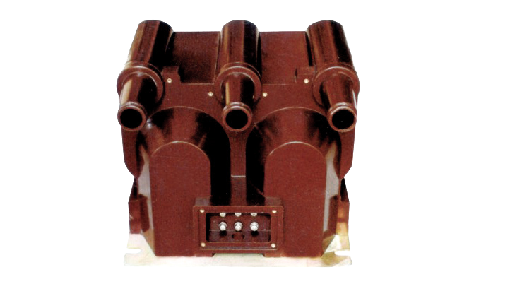
Product Shows

Working Principle
Operating on Faraday’s law of electromagnetic induction, the combined voltage transformer features high-grade silicon steel laminated cores with primary windings connected to the system voltage and secondary windings delivering standardized output voltages. The dual-output configuration provides 100 V for precision metering and energy measurement, while the 220 V output serves as auxiliary power for control systems, circuit breakers, and protection relays. Integrated high-voltage fuses on each phase primary winding provide short-circuit protection and prevent fault propagation.
System Application Position
- Medium Voltage Distribution: 10kV indoor switchgear, distribution panels, and ring main units
- Energy Metering: Revenue-grade voltage measurement for electricity billing systems
- Auxiliary Power Supply: 220 V AC power source for circuit breaker control, protection relays, and monitoring equipment
- Protection Circuits: Voltage-dependent protection schemes including overvoltage, undervoltage, and earth fault detection
- SCADA Integration: Voltage monitoring and data acquisition in supervisory control systems
Structural Overview
Fully-enclosed epoxy resin cast construction with premium cold-rolled silicon steel cores ensures superior insulation performance, moisture resistance, and long-term stability. The combined design integrates dual secondary outputs in a compact footprint suitable for indoor switchgear environments. Integrated fuse protection on all three phases provides reliable short-circuit interruption with easy fuse replacement via accessible secondary terminals without affecting operation.
Model Designation

Model Code Explanation
- J — Combined instrument transformer (voltage + protection)
- S — Indoor type (室内)
- Z — Cast-resin (epoxy) insulated, fully enclosed structure
- V — Voltage transformer function
- 12 — Design series / platform iteration
- 10 — Voltage class (kV)
- R — Integrated fuse protection (熔断器)
Configuration Options
The JSZV12-10R is available in multiple voltage class variants (10kV, 6kV, 3kV) and output configurations:
- JSZV12-10R: 10kV class with dual output (100V metering + 220V auxiliary power)
- JSZV12-6R: 6kV class variant
- JSZV12-3R: 3kV class variant
- JSZV-10-10R: Alternative 10kV configuration with single 100V output
All variants feature integrated fuse protection and fully-enclosed epoxy resin construction. Selection depends on system voltage class and output requirements.
Service Conditions
The JSZV12-10R series combined voltage transformers are designed for indoor operation under normal service conditions in medium-voltage power systems.
- Installation environment: Indoor installation only
- Altitude: Not exceeding 1000 m above sea level (higher altitude configurations available upon engineering confirmation)
- Ambient temperature: −5 °C to +40 °C
- Relative humidity: ≤ 80% (without condensation)
- Environmental conditions: Free from corrosive gases, vapors, or conductive deposits; free from explosive or flammable media; no conductive dust (carbon, metallic particles); no severe vibration, mechanical shock, or impact
Construction
Construction Design
- Structure: Fully-enclosed combined type for indoor switchgear integration
- Insulation: Epoxy resin cast insulation system with superior dielectric properties
- Core material: Premium cold-rolled silicon steel laminations for low losses and high accuracy
- Fuse integration: High-voltage fuses on A, B, C phase primary windings with coordinated interrupting capacity
- Secondary terminals: Accessible terminal blocks for easy fuse replacement without affecting operation
- Configuration: Three-phase V-connection or two independent single-phase units
The epoxy resin casting provides stable insulation properties and resistance to moisture, contamination, tracking, and aging for long-term indoor service. The integrated fuse design prevents fault propagation and enhances system reliability.
Windings & Terminal Marking
- Primary terminals (per phase): A / B / C (high-voltage side)
- Secondary terminals (100V metering): a / x (per phase)
- Secondary terminals (220V auxiliary): a1 / x1 (where applicable)
- Neutral/ground terminal: N or dedicated grounding point
Terminal markings follow standard voltage transformer polarity conventions. Under normal operating conditions, when primary terminal A is positive, secondary terminal a is positive (additive polarity). Correct terminal identification shall be observed to ensure metering accuracy and protection coordination.
Technical Data
This section provides selection-oriented technical data for the JSZV12-10R series indoor, fully-enclosed combined voltage transformer with integrated fuses, used in 10 kV class AC systems (50 Hz). Data shown below is intended for preliminary selection of voltage ratios, accuracy class combinations, rated burdens, and dual-output configurations.
Definitions: Accuracy class combination indicates available metering accuracy grades per output. Rated burden (VA) is specified per secondary circuit. Maximum output is the short-time overload capability. Insulation level follows Um/Ud/Up notation per GB 311.1-2012.
Notation: Dual-output models provide both 100V (metering) and 220V (auxiliary power); single-output models provide 100V only. Acceptance shall be based on nameplate values and the factory test report.
Data Reference
Auxiliary Power Output Specifications (Circuit Breaker Control / Relay Supply)
| Type | Rated Voltage Ratio (V) |
Accuracy Class & Rated Output (VA) |
Max Output (VA) |
Rated Insulation Level (KV) |
|||
|---|---|---|---|---|---|---|---|
| 0.2 | 0.5 | 1 | 6p | ||||
| JSZW3-10 | 10000/3/100/3/100/3 | 15 | 30 | 60 | 50 | 300 | 12/42/75 |
| JSZW3-6 | 6000/3/100/3 | 7.2/32/60 | |||||
| JSZW3-3 | 3000/3/100/3 | 3.6/20/40 | |||||
Standards & Normative References
| Standard | Title | Application |
|---|---|---|
| GB/T 20840.3-2013 | Instrument Transformers – Part 3: Electromagnetic Voltage Transformers | Primary voltage transformer requirements |
| GB/T 20840.4-2015 | Instrument Transformers – Part 4: Combined Transformers | Combined instrument transformer specific requirements |
| GB 311.1-2012 | Insulation Coordination for High-Voltage Transmission Equipment | Insulation level specification and coordination |
| JJG 314-2010 | Verification Regulation of Voltage Transformers | Accuracy verification and calibration procedures |
| IEC 61869-3 | Instrument Transformers – Part 3: Additional Requirements for Inductive Voltage Transformers | International voltage transformer requirements (reference) |
| IEC 61869-5 | Instrument Transformers – Part 5: Additional Requirements for Combined Transformers | International combined transformer requirements (reference) |
| GB/T 16927 | High-Voltage Test Techniques | Dielectric test procedures |
| DL/T 866 | Technical Specification for Voltage Transformers in Power Systems | Power system application guidelines (where applicable) |
Factory Test Compliance
- Routine tests per applicable GB/IEC requirements (including polarity/marking verification, ratio accuracy, phase displacement, and burden accuracy per specified class)
- Dielectric tests per insulation coordination requirements (power-frequency withstand, impulse withstand per GB 311.1-2012)
- Partial discharge test where specified by project requirement or applicable standard
- Temperature rise test to verify thermal performance under rated and maximum burden conditions
- Fuse coordination test to verify integrated fuse interrupting capability and selectivity
- Visual and dimensional inspection including marking conformity and workmanship verification
- Type and special tests as required by project specification or certification authority
Installation & Dimensions
Installation Environments
- Outline dimensions and mounting details are provided in the dimensional drawings.
- The combined transformer shall be securely mounted using the designated fixing holes or bracket assembly.
- Primary connection may be made via busbar or bolted cable terminals depending on switchgear configuration.
- Secondary circuits shall be wired to designated terminal blocks maintaining proper phase identification.
- Adequate clearance shall be maintained for insulation coordination, heat dissipation, fuse accessibility, and maintenance access.
- Fuse replacement can be performed via secondary terminal access without de-energizing the installation (per manufacturer procedure).
Outlines

Connection Diagrams
Three-phase V-connection (standard configuration):
- Two single-phase units connected in open-delta (V) configuration
- Provides three-phase voltage measurement capability with two transformers
- Primary terminals: A-N, B-N (or A-B-C for wye-connected systems)
- Secondary 100V terminals: a-x (per phase)
- Secondary 220V terminals: a1-x1 (where applicable for auxiliary power)
Safety Notes
- Secondary circuits must never be left open when the transformer is energized, as dangerous high voltage may appear across open terminals.
- During inspection or maintenance, de-energize primary circuits or follow manufacturer lock-out/tag-out procedures.
- Fuse replacement shall be performed only by qualified personnel following manufacturer instructions.
- One point of each secondary circuit shall be reliably grounded in accordance with GB 50150 or applicable local standards.
- The 220V auxiliary power output shall be protected by appropriately rated secondary circuit breakers or fuses per load requirements.
- All installation and maintenance work shall comply with DL 408 (Electric Power Safety Work Regulations) or local electrical safety regulations.
Ordering Information
When placing an order, the required configuration shall be specified according to the local grid requirements, applicable standards, and project technical specification. The following parameters shall be clearly stated for technical confirmation and production release:
Selection Guidance
- System voltage class (10kV, 6kV, or 3kV)
- Voltage ratio (primary/secondary voltages)
- Output configuration (dual 100V+220V or single 100V)
- Accuracy requirements (0.2 or 0.5 class)
- Rated burden (VA) per secondary circuit
- Connection configuration (V-connection or single-phase)
- Insulation level (if non-standard)
- Fuse rating (if specific coordination required)
For applications with extended temperature range, higher altitude operation, enhanced corrosion protection, specific fuse coordination, or special certificates, specify requirements at ordering stage. Custom configurations require technical agreement and final data sheet confirmation prior to production.
Customization Options
Available upon request:
- Extended temperature range: Operation beyond −5°C to +40°C standard range
- Custom voltage ratios: Non-standard primary or secondary voltages
- Enhanced environmental protection: Conformal coating or special sealing for corrosive environments
- Alternative output configurations: Custom secondary voltage or burden combinations
- Specific fuse coordination: Custom fuse ratings for project protection schemes
- High-altitude operation: Enhanced insulation for installations above 1000m elevation