Product Overview
Functional Definition
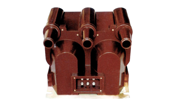
The JSZV12-20R three-phase epoxy resin combination voltage transformer with built-in fuse protection is specifically designed for XGW-12 outdoor AC fixed metal-enclosed switchgear applications. This voltage transformer provides both 100V measurement voltage output and 220V operating power supply, delivering stable power to circuit breakers while ensuring reliable operation and system efficiency.
Key Ratings
| Item | Specification |
|---|---|
| System voltage class | 12 kV class (outdoor switchgear applications, rated 20 kV) |
| Rated frequency | 50 Hz |
| Rated primary voltage | 20 kV / √3 |
| Rated secondary voltage | 100V, 220V (as specified) |
| Accuracy classes | 0.2, 0.5 (metering applications) |
| Primary connection | V-connection (open-delta) |
| Fuse protection | Built-in primary winding fuse protection |
| Insulation level | 24/65/125 kV (Um/Ud/Up) |
| Applicable standards | GB 1207-1997 |
Working Principle
Operating on electromagnetic induction principles, the voltage transformer features three-phase epoxy resin cast cores with primary and secondary windings. The transformer steps down high voltage to standardized measurement and auxiliary supply voltages, providing galvanically isolated secondary outputs proportional to primary voltage. The V-connection configuration enables voltage measurement with two single-phase units while also detecting ground faults in the system.
System Application Position
- Medium Voltage Distribution: 12-20kV outdoor metal-enclosed switchgear (XGW-12 series)
- Voltage Metering: Revenue-grade electricity measurement and voltage monitoring systems
- Auxiliary Power Supply: Providing operating power for circuit breaker control and protection circuits
- Protection Schemes: Overvoltage, undervoltage, and ground fault protection applications
Structural Overview
Epoxy resin cast construction with fully-enclosed design ensures superior insulation performance, moisture resistance, and mechanical strength. The built-in fuse protection located at the primary output terminals provides easy replacement and maintenance access. The compact structure integrates voltage measurement and auxiliary power supply functions in a single unit, optimizing installation space in metal-enclosed switchgear environments.
Model Designation

Model Code Explanation
- J — Voltage transformer (VT)
- S — Three-phase configuration
- Z — Cast-resin (epoxy) insulated structure
- V — V-connection (open-delta) configuration
- 12 — Voltage class (kV)
- 20 — Rated voltage (kV)
- R — Built-in fuse protection
Service Conditions
The JSZV12-20R voltage transformer is designed for outdoor metal-enclosed switchgear installation under normal service conditions in medium-voltage power systems.
- Installation environment: Outdoor metal-enclosed switchgear (XGW-12)
- Altitude: ≤1000 m above sea level (pollution level II)
- Ambient temperature: −5°C to +40°C
- Relative humidity: ≤80%
- Environmental conditions: Free from corrosive gases or vapor; free from carbon dust or conductive metallic dust; no severe vibration or mechanical shock
Construction
Construction Design
- Structure: Three-phase combination type for outdoor switchgear
- Insulation: Fully enclosed epoxy resin cast insulation
- Connection: V-connection (open-delta) configuration
- Protection: Built-in fuse at primary output terminals
- System: Integrated voltage measurement and auxiliary power supply
The epoxy resin casting provides stable insulation properties with excellent resistance to moisture, contamination, and aging for long-term outdoor switchgear service. The built-in fuse protection system prevents primary winding short-circuit conditions, enhancing overall system safety and reliability.
Windings & Terminal Marking
- Primary terminals: A, B, C (phase connections)
- Secondary terminals (100V): a, b, c, n (measurement voltage output)
- Secondary terminals (220V): 110V and 220V auxiliary power terminals
Terminal markings follow standard VT polarity conventions. Correct terminal identification shall be observed to ensure metering accuracy and protection performance. The auxiliary power terminals provide stable operating voltage for circuit breaker control circuits and protection relays.
Technical Data
This section provides selection-oriented technical data for the JSZV12-20R three-phase epoxy resin combination voltage transformer with built-in fuse used in 12-20 kV class AC systems (50 Hz). Data shown below is intended for preliminary selection of voltage ratio, accuracy class, and rated output capacity.
Definitions: Accuracy class indicates metering performance level. Rated output (VA) is the maximum burden that can be connected while maintaining specified accuracy. Load power factor is assumed as cosφ = 0.8 (lagging).
Data Reference
| Model | Rated Voltage Ratio (V) |
Class 0.2 Output (VA) |
Class 0.5 Output (VA) |
Rated Insulation Level (kV) |
|---|---|---|---|---|
| JSZV12-20R | 20000/100 | 30 | 50 | 24/65/125 |
| JSZV12-20R | 20000/100/100 | 20 | 50 | 24/65/125 |
| JSZV12-20R | 20000/220 | 20 | 50 | 24/65/125 |
| JSZV12-20R | 20000/100/220 | 20 | 50 | 24/65/125 |
Standards & Normative References
| Standard | Title | Application |
|---|---|---|
| GB 1207-1997 | Voltage Transformers | VT general requirements and testing |
| IEC 61869-3 | Instrument Transformers – Part 3: Voltage Transformers | Optional (international reference) |
Factory Test Compliance
- Routine tests per GB 1207-1997 requirements (including polarity verification, ratio verification, and accuracy verification per specified class and burden)
- Dielectric tests per insulation coordination requirements and applicable standard
- Visual and dimensional inspection including marking and workmanship conformity
- Type and special tests as required by the project specification
Installation & Dimensions
Outline

Principle diagram

- Outline dimensions and mounting details are provided in the switchgear documentation
- The transformer shall be securely mounted using the designated fixing holes within the XGW-12 switchgear compartment
- Primary connections are made via busbar terminals integrated with the switchgear design
- Adequate clearance shall be maintained for insulation, heat dissipation, and maintenance access
- Built-in fuse protection is accessible from the front panel for easy replacement
Safety Notes
- Secondary circuit must be properly grounded in accordance with applicable standards
- During inspection or maintenance, the primary circuit shall be de-energized and properly isolated
- Fuse replacement shall only be performed by qualified personnel following proper safety procedures
- All installation and maintenance work shall comply with local electrical safety regulations
Ordering Information
When placing an order, the required configuration shall be specified according to the local grid requirements, applicable standards, and project technical specification. The following parameters shall be clearly stated for technical confirmation and production release:
- Rated voltage ratio (primary/secondary voltage)
- Rated secondary voltage (100V, 220V, or combined configuration)
- Accuracy class (0.2 or 0.5 for metering applications)
- Rated burden (VA) for each secondary winding
- Application requirements (voltage measurement and/or auxiliary power supply)
If local utility or project requirements apply (e.g., insulation level, terminal arrangement, mounting constraints, documentation language, or required certificates), specify them at the ordering stage. Special configurations shall be confirmed by technical agreement and final data sheet prior to production.