Product Overview
Functional Definition
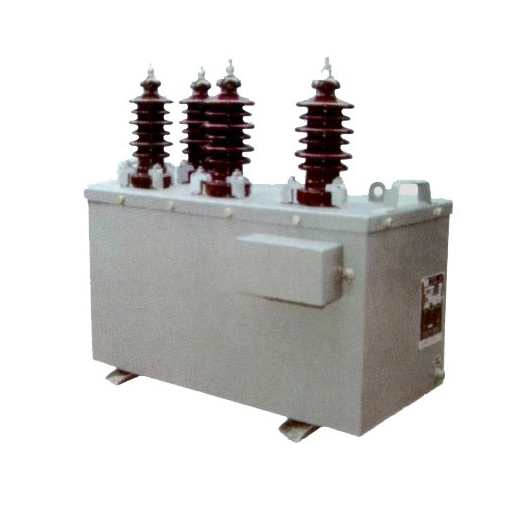
The JSZW-10 series 10KV Three-Phase Outdoor Epoxy Resin Voltage Transformer, are precision electromagnetic instruments designed for accurate voltage measurement, energy metering, and relay protection applications in 10kV outdoor AC power systems. These transformers utilize electromagnetic induction principles to provide galvanically isolated secondary voltage signals proportional to primary voltage, suitable for outdoor distribution applications at rated frequency of 50 Hz.
Key Ratings
| Item | Specification (per order / nameplate) |
|---|---|
| System voltage class | 10 kV class (outdoor distribution applications) |
| Rated frequency | 50 Hz (60 Hz available upon request) |
| Rated voltage ratio | 10000/√3 / 100/√3 / 100/√3 (V) |
| Accuracy classes | 0.2, 0.5, 3P (metering and protection cores as specified) |
| Rated output | 0.2 class: 75 VA; 0.5 class: 120 VA; 3P class: 120 VA |
| Maximum output | 960 VA |
| Burden power factor | cosφ = 0.8 (lagging) unless otherwise specified by the project standard |
| Insulation level | 12/42/75 kV (Um/Up/Ud) per applicable standard |
| Creepage distance | Compliant with pollution class II requirements |
| Applicable standards | GB 20840.3-2013, GB 20840.1-2010 (Voltage Transformers); IEC 61869-3 / IEC 61869-1 |
| Installation type | Outdoor, post-type mounting |
Working Principle
Operating on Faraday’s law of electromagnetic induction, the voltage transformer features a laminated core with primary and secondary windings electrically isolated. The primary winding, connected to the high-voltage system, induces a proportional voltage in the secondary winding(s), delivering standardized low-voltage output signals through connected burden. The fully-enclosed epoxy resin cast construction ensures stable operation in outdoor environments.
System Application Position
- Medium Voltage Distribution: 10kV outdoor switchgear and distribution systems
- Energy Metering: Revenue-grade electricity measurement systems for outdoor installations
- Protection Circuits: Overvoltage, undervoltage, and directional protection schemes
- SCADA Integration: Supervisory control and data acquisition systems in outdoor substations
Structural Overview
Epoxy resin cast construction with fully-enclosed design ensures superior insulation performance, moisture resistance, UV protection, and mechanical strength for outdoor service. The post-type mounting configuration provides reliable installation in outdoor distribution equipment while maintaining excellent electrical clearance and creepage distances. The sealed support structure and German CY160 epoxy material provide resistance to environmental contamination and temperature variations.
Model Designation

Model Code Explanation
- J — Voltage transformer (VT)
- S — Three-phase configuration
- Z — Cast-resin (epoxy) insulated, fully enclosed structure
- W — Outdoor (weather-resistant) type
- 10 — Voltage class (kV)
Service Conditions
The JSZW-10 series voltage transformers are designed for outdoor operation under specified service conditions in medium-voltage power distribution systems.
- Installation environment: Outdoor installation
- Altitude: Not exceeding 3000 m above sea level (higher altitude shall be specified for engineering confirmation)
- Ambient temperature: −5 °C to +40 °C
- Relative humidity: Daily average ≤ 85% (at +20 °C reference)
- Environmental conditions: Free from corrosive gases or vapors; suitable for outdoor exposure with pollution class II creepage distance compliance; no severe vibration, mechanical shock, or impact
Construction
Construction Design
- Structure: Post-type for outdoor distribution equipment
- Insulation: Fully enclosed epoxy resin cast insulation (German CY160 material)
- Core: Laminated magnetic core design
- Housing: Sealed support structure with integrated base plate
- Environmental protection: UV-resistant, moisture-resistant, pollution-resistant for outdoor service
The epoxy resin casting provides stable insulation properties and resistance to moisture, UV radiation, temperature cycling, contamination, and aging for long-term outdoor service. The C-type core design offers excellent magnetic performance.
Windings & Terminal Marking
- Primary terminals: A / B / C (high-voltage side)
- Secondary terminals (Metering): a1 / b1 / c1 / n1
- Secondary terminals (Protection, if applicable): a2 / b2 / c2 / n2
Terminal markings follow standard VT polarity conventions. All secondary terminals are housed in a sealed terminal box. Correct terminal identification shall be observed to ensure metering and protection performance.
Technical Data
This section provides selection-oriented technical data for the JSZW-10 series outdoor, three-phase, cast-resin voltage transformer used in 10 kV class AC systems (50 Hz). Data shown below is intended for preliminary selection of accuracy class combinations, rated outputs, and insulation levels.
Definitions: Accuracy class indicates metering or protection application suitability. Rated output (VA) is specified per secondary winding. Insulation level is expressed as Um/Up/Ud (highest voltage for equipment / power-frequency withstand / lightning impulse withstand).
Notation: Multiple voltage ratios may be available but only one ratio shall be used during operation; simultaneous use of multiple ratios is prohibited.
Data Reference
| Model | Rated Voltage Ratio (V) |
Accuracy Class |
Rated Output (VA) |
Maximum Output (VA) |
Rated Insulation Level (kV) |
|---|---|---|---|---|---|
| JSZW-6 | 6000/√3 / 100/√3 / 100/√3 | 0.2 | 75 | 960 | 7.2/32/60 |
| 0.5 | 120 | ||||
| 3P | 120 | ||||
| JSZW-10 | 10000/√3 / 100/√3 / 100/√3 | 0.2 | 75 | 960 | 12/42/75 |
| 0.5 | 120 | ||||
| 3P | 120 |
Standards & Normative References
| Standard | Title | Application |
|---|---|---|
| IEC 61869-1 | Instrument Transformers – Part 1: General Requirements | General requirements |
| IEC 61869-3 | Instrument Transformers – Part 3: Additional Requirements for Inductive Voltage Transformers | VT-specific requirements |
| GB 20840.1-2010 | Instrument Transformers – Part 1: General Requirements | National standard (aligned with IEC 61869 framework) |
| GB 20840.3-2013 | Instrument Transformers – Part 3: Voltage Transformers | National VT requirements (aligned with IEC 61869-3) |
| GB/T 22071.1 | Insulation Coordination for Low-Voltage Systems – Part 1: Principles, Requirements and Tests | Insulation coordination reference |
| IEC 60060-1 | High-Voltage Test Techniques – Part 1: General Definitions and Test Requirements | High-voltage testing procedures |
| IEC 60085 | Electrical Insulation – Thermal Evaluation | Insulation thermal evaluation reference |
Factory Test Compliance
- Routine tests per applicable IEC/GB requirements (including polarity/marking, ratio verification, and accuracy verification per specified class and burden)
- Dielectric tests per insulation coordination requirements and applicable standard (power-frequency withstand and lightning impulse tests)
- Partial discharge test where specified by the project requirement
- Visual and dimensional inspection including marking, creepage distance verification, and workmanship conformity
- Type and special tests as required by the project specification
Installation Dimensions

- Outline dimensions and mounting details are provided in the dimensional drawings.
- The transformer shall be securely mounted using the designated fixing holes on the base plate.
- Primary connections shall be made to the high-voltage terminals (A, B, C) with appropriate clearances.
- Secondary connections are accessed through the sealed terminal box with standard screw terminals.
- Adequate clearance shall be maintained for insulation, heat dissipation, and maintenance access.
- Installation shall comply with local electrical codes and outdoor equipment mounting practices.
Safety Notes
- Secondary circuit should not be left open when the transformer is energized, as this may affect measurement accuracy and potentially damage connected equipment.
- During inspection or maintenance, the primary circuit shall be de-energized and proper lockout/tagout procedures followed.
- One point of the secondary circuit should be reliably grounded in accordance with applicable standards.
- All installation and maintenance work shall comply with local electrical safety regulations for outdoor medium-voltage equipment.
- Periodic inspection of the epoxy housing for cracks, contamination, or UV degradation is recommended.
Ordering Information
When placing an order, the required configuration shall be specified according to the local grid requirements, applicable standards, and project technical specification. The following parameters shall be clearly stated for technical confirmation and production release:
- Rated voltage ratio (primary voltage / secondary voltage)
- Accuracy class requirements (metering and/or protection accuracy class)
- Rated output (VA) for each secondary winding
- Insulation level (if different from standard 12/42/75 kV for JSZW-10)
- Environmental conditions (altitude, pollution class, temperature range if exceeding standard conditions)
- Special requirements (if applicable: additional secondary windings, special terminals, documentation language, certificates)
If local utility or project requirements apply (e.g., special creepage distance, terminal arrangement, mounting constraints, documentation language, or required certificates), specify them at the ordering stage. Special configurations shall be confirmed by technical agreement and final data sheet prior to production.