Product Overview
Functional Definition
The LAJ-10Q and LFZBJ-10 series current transformers are through-wall type, epoxy resin cast precision electromagnetic instruments designed for accurate current measurement, energy metering, and relay protection applications in medium-voltage AC power systems. The LAJ-10Q series is specifically engineered for demanding operational environments, providing stable and reliable performance under complex and harsh conditions. These transformers utilize electromagnetic induction principles to provide galvanically isolated secondary current signals proportional to primary current.
Key Ratings
| Item | Specification (per order / nameplate) |
|---|---|
| System voltage class | 10 kV class (indoor/outdoor distribution applications) |
| Rated frequency | 50 Hz or 60 Hz |
| Rated secondary current | 5 A (standard) |
| Accuracy classes | Metering and/or protection cores: 0.2S, 0.2, 0.5, 10P10, 10P15 |
| Rated burden | Per core/winding as specified (VA): 10-15 VA typical |
| Burden power factor | cosφ = 0.8 (lagging) unless otherwise specified |
| Short-circuit withstand | Ith: Up to 40 kA (1 s); Idyn: Up to 90 kA (peak) |
| Primary current range | 5 A to 3000 A |
| Applicable standards | IEC 61869-1 / IEC 61869-2; GB/T 20840.1 / 20840.2; GB 1208-1997; IEC 60044-1 |
| Mechanical variants | LAJ-10 / LAJ-10Q / LFZBJ-10 (Single-turn, multi-turn, busbar types) |
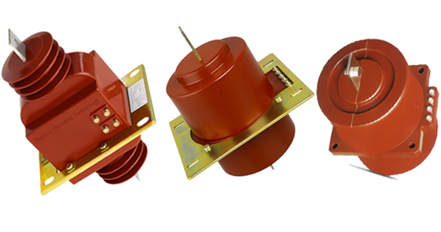
Product Shows
 Thomas Electric")
Working Principle
Operating on Faraday’s law of electromagnetic induction, the transformer features a toroidal magnetic core with primary conductor passing through the window aperture and secondary windings wound around the core. The magnetic flux generated by primary current induces proportional voltage in the secondary winding, delivering standardized output current through connected burden. The epoxy resin encapsulation ensures complete insulation and protection against environmental factors.
System Application Position
- Medium Voltage Distribution: 10kV switchgear, distribution panels, and power distribution systems
- Energy Metering: Revenue-grade electricity measurement systems with 0.2S class accuracy
- Protection Circuits: Overcurrent, differential, and distance protection schemes (10P10, 10P15 class)
- SCADA Integration: Supervisory control and data acquisition systems
- Harsh Environment Applications: LAJ-10Q variant specifically designed for challenging operational conditions
Structural Overview
The LAJ-10Q series through-wall type current transformers are available in three structural configurations: single-turn, multi-turn, and busbar type arrangements, all featuring epoxy resin cast construction with fully-enclosed or semi-enclosed design. Products rated 300A and below utilize semi-enclosed structure for ease of installation, while 400-800A ratings employ fully sealed construction for enhanced environmental protection and mechanical strength. The through-wall mounting configuration enables compact installation in switchgear while maintaining excellent electrical clearance and creepage distances.
Model Designation
 Thomas Electric")
Model Code Explanation
LAJ-10 / LAJ-10Q
- L = Current Transformer (CT)
- A = Bulkhead / Through-wall mounting (panel or wall-mounted)
- J = Enhanced / reinforced design (mechanical & insulation robustness)
- Q = All-condition (full-duty) variant — designed for complex/harsh operating conditions
- 10 = Voltage class 10 kV
LFZBJ-10 (10 kV class)
- L = Current Transformer (CT)
- F = Cast-resin insulated (epoxy resin casting)
- Z = Busbar separated / busbar arrangement (structure-related code)
- B = With protection function option (protection core configuration available)
- J = Enhanced / reinforced design
- 10 = Voltage class 10 kV
Variant Differences
LAJ-10: Standard through-wall current transformer for general indoor applications with normal environmental conditions.
LAJ-10Q: All-conditions enhanced variant designed specifically for harsh and complex operational environments. Features improved environmental resistance while maintaining all electrical specifications of the standard LAJ-10 series.
LFZBJ-10: Indoor support-type variant with enclosed construction, suitable for standard switchgear installations where through-wall mounting is not required.
All variants are electrically equivalent when specified with the same ratio, accuracy classes, burdens, and Ith/Idyn ratings. Selection between variants is based on mounting constraints and environmental conditions.
Service Conditions
The LAJ-10Q series current transformers are designed for operation under normal and harsh service conditions in medium-voltage power systems.
Standard Operating Environment
- Installation environment: Indoor or outdoor installation (LAJ-10Q rated for harsh conditions)
- Altitude: Not exceeding 1000 m above sea level (higher altitude applications require engineering confirmation)
- Ambient temperature: −5 °C to +40 °C
- Relative humidity: ≤ 90% at +20 °C reference temperature
- Environmental conditions: Free from corrosive gases, chemical contamination, or substances affecting insulation performance; no severe vibration, mechanical shock, or impact
Enhanced Environment Rating
- Harsh environment capability: Specifically designed for complex and demanding operational conditions
- Enhanced protection: Superior resistance to moisture, contamination, and thermal cycling
- Operational reliability: Maintains performance under adverse environmental conditions
Construction
Construction Design
- Structure: Through-wall (bushing) type for panel/wall mounting; Support type available (LFZBJ-10)
- Insulation: Epoxy resin cast insulation (fully enclosed or semi-enclosed depending on rating)
- Core: High-quality silicon steel laminations in ring-type configuration
- Primary winding: Single-turn, multi-turn, or busbar conductor through window aperture
- Secondary winding: Precision-wound coils on toroidal core
- Enclosure rating: Semi-enclosed (≤300A); Fully sealed (400-800A)
The epoxy resin casting provides stable insulation properties, excellent mechanical strength, and resistance to moisture, contamination, and aging for long-term service. The LAJ-10Q variant features enhanced material formulation for superior performance in harsh environments.
Windings & Terminal Marking
- Primary terminals: P1 / P2 (busbar exits from both ends for through-wall mounting)
- Secondary terminals (Group 1): S1 / S2 (1S1 / 1S2 for multi-core units)
- Secondary terminals (Group 2): 2S1 / 2S2 (where applicable for dual-core configuration)
- Terminal location: Secondary terminals positioned at bottom mounting side for convenient access
- Terminal type: Exposed screw terminals for ease of connection
Terminal markings follow standard CT polarity conventions per IEC 61869-2 and GB 1208-1997. Under normal operating conditions, the reference current direction is defined from P1 to P2. Correct terminal identification shall be observed to ensure proper metering and protection performance.
Technical Data
This section provides selection-oriented technical data for the LAJ-10Q and LFZBJ-10 series through-wall and support-type, cast-resin current transformers used in 10 kV class AC systems (50 Hz / 60 Hz). Data shown below is intended for preliminary selection of accuracy class combinations, rated burdens, and short-circuit withstand capability.
Definitions:
Accuracy class combination indicates available metering/protection cores in one CT (multi-core configuration may apply).
Rated output (VA) is specified per secondary core.
Ith is the rated short-time thermal current (1 s duration).
Idyn is the rated dynamic current (peak value).
Notation: All values shown are per nameplate and factory test report. Customization is available for specific project requirements.
Data Reference
| Rated Primary Current (A) |
Accuracy Class Combination |
Rated Output (VA) | Rated Short-time Current (kA/1s) |
Rated Dynamic Current (kA) |
||||
|---|---|---|---|---|---|---|---|---|
| 0.2S | 0.2 | 0.5 | 10P10 | 10P15 | ||||
| 5~100 | 0.2S/0.2S
0.210.2 0.2S/10P10 0.2/10P10 0.5/10P10 0.2/10P15 0.5/10P15
|
10 | 10 | 10 | 15 | 15 | 100|1n | 250|1n |
| 150 | 13.5 | 34 | ||||||
| 200 | 18 | 45 | ||||||
| 300 | 27 | 67 | ||||||
| 400 | 30 | 75 | ||||||
| 500 | 36 | 90 | ||||||
| 600 | ||||||||
| 750 | 40 | |||||||
| 800 | ||||||||
| 1000 | – | – | ||||||
| 2000~3000 | ||||||||
Standards & Normative References
| Standard | Title | Application |
|---|---|---|
| IEC 61869-1 | Instrument Transformers – Part 1: General Requirements | General requirements for instrument transformers |
| IEC 61869-2 | Instrument Transformers – Part 2: Additional Requirements for Current Transformers | CT-specific requirements and testing procedures |
| GB/T 20840.1 | Instrument Transformers – Part 1: General Requirements | National standard (aligned with IEC 61869 framework) |
| GB/T 20840.2 | Instrument Transformers – Part 2: Current Transformers | National CT requirements (aligned with IEC 61869-2) |
| GB 1208-1997 | Current Transformers | National CT standard for electrical performance |
| IEC 60044-1 | Instrument Transformers – Part 1: Current Transformers | International standard reference |
| IEEE C57.13 | Standard Requirements for Instrument Transformers | Optional (North America project reference) |
Factory Test Compliance
- Routine tests per applicable IEC/GB requirements (including polarity/marking verification, ratio verification, and accuracy verification per specified class and burden)
- Dielectric tests per insulation coordination requirements and applicable standard (power frequency withstand voltage test)
- Partial discharge test where specified by the project requirement
- Visual and dimensional inspection including marking verification and workmanship conformity
- Temperature rise test for rated continuous current
- Short-circuit withstand test (Ith and Idyn) per project specification
- Type and special tests as required by the project specification
Installation & Dimensions
- Outline dimensions and mounting details vary by current rating and structural type (single-turn, multi-turn, busbar)
- The transformer shall be securely mounted using the designated fixing holes and hardouware
- Primary conductor connection is made via busbar passing through the window aperture
- Adequate clearance shall be maintained for insulation coordination, heat dissipation, and maintenance access
- Through-wall mounting requires proper panel cutout dimensions per rating
- Consult factory dimensional drawings for specific current rating and variant
Outline
 Thomas Electric")
Mounting Configurations
Through-Wall Type (LAJ-10, LAJ-10Q):
- Primary busbar passes through panel wall opening
- Mounting flanges secure transformer to panel surface
- Secondary terminals accessible from bottom mounting side
Support Type (LFZBJ-10):
- Post-type mounting on switchgear base plate
- Suitable for indoor enclosed switchgear applications
- Compact footprint for space-constrained installations
Safety Notes
- Secondary circuit must never be left open when the transformer is energized, as dangerous high voltage may appear across the secondary terminals
- During inspection or maintenance, the secondary circuit shall be short-circuited before disconnecting any instruments
- One point of the secondary circuit should be reliably grounded in accordance with applicable standards (IEC 61869, GB standards, local codes)
- All installation and maintenance work shall comply with local electrical safety regulations
- Proper personal protective equipment (PPE) shall be used during installation and servicing
- Verify de-energization of primary circuit before performing any maintenance work
Ordering Information
When placing an order, the required configuration shall be specified according to the local grid requirements, applicable standards, and project technical specification. The following parameters shall be clearly stated for technical confirmation and production release:
Required Specification Parameters
- Rated primary current / transformation ratio (e.g., 100/5A, 200/5A, 600/5A)
- Rated secondary current (5 A standard; 1 A available upon request)
- Application and accuracy requirements (metering and/or protection accuracy class combination)
- Rated burden (VA) for each secondary core/winding
- Short-circuit withstand requirements: Ith (1 s) and Idyn (peak) based on system fault level
- Variant selection: LAJ-10 (standard), LAJ-10Q (harsh environment), or LFZBJ-10 (support type)
- Structural type: Single-turn, multi-turn, or busbar configuration
Optional Specifications (if applicable)
- Insulation level requirements beyond standard
- Partial discharge limit (if specified)
- Terminal arrangement preferences
- Mounting constraints or dimensional requirements
- Documentation language preferences
- Required certificates (type test, routine test, material certificates)
- Special environmental conditions (temperature, humidity, altitude)
If local utility or project requirements apply (e.g., specific insulation coordination, partial discharge limits, terminal arrangements, mounting constraints, documentation language, or certification requirements), specify them at the ordering stage. Special configurations shall be confirmed by technical agreement and final data sheet prior to production.
FAQs