Product Overview
Functional Definition
The LB-10W series Outdoor Oil-Immersed Current Transformers are precision electromagnetic instruments designed for accurate current measurement, energy metering, and relay protection applications in 10 kV medium-voltage AC power systems. These oil-immersed transformers utilize electromagnetic induction principles with steel-tank construction to provide galvanically isolated secondary current signals proportional to primary current, suitable for both indoor and outdoor installations.
Key Ratings
| Item | Specification (per order / nameplate) |
|---|---|
| System voltage class | 10 kV class (indoor and outdoor applications) |
| Rated frequency | 50 Hz |
| Rated secondary current | 5 A |
| Rated primary current range | 20 A to 400 A |
| Continuous thermal rating | 120% of rated primary current (continuous operation) |
| Accuracy classes | Metering: 0.2, 0.5; Protection: 10P10 |
| Rated burden | 10 VA, 15 VA, 20 VA per core/winding as specified |
| Burden power factor | cosφ = 0.8 (lagging) unless otherwise specified |
| Short-circuit withstand | Ith: 1.8 kA to 30 kA (1 s); Idyn: 3.0 kA to 50 kA (peak) per rating |
| Thermal stability factor | 187.5 (high thermal loading capability) |
| Insulation medium | Mineral insulating oil with vacuum filtration and vacuum oil-filling process |
| Applicable standards | IEC 61869-1 / IEC 61869-2; GB/T 20840.1 / 20840.2; GB 1208-1997 |
| Installation location | Indoor or outdoor |
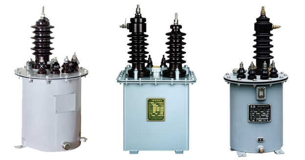
Product Shows
 Thomas Electric")
Working Principle
Operating on Faraday’s law of electromagnetic induction, the transformer features a toroidal magnetic core with primary conductor passing through the aperture and secondary windings wound around the core. The magnetic flux generated by primary current induces proportional voltage in the secondary winding, delivering standardized output current through connected burden. The oil-immersed design provides superior insulation and thermal management for outdoor environments.
System Application Position
- Medium Voltage Distribution: 10kV switchgear, distribution panels, and outdoor substations
- Energy Metering: Revenue-grade electricity measurement systems with 0.2 and 0.5 class accuracy
- Protection Circuits: Overcurrent, differential, and distance protection schemes (10P10 class)
- Outdoor Applications: Pole-mounted installations, overhead line monitoring, and exposed distribution equipment
- High-Altitude Installations: Suitable for installations up to 4000 m above sea level with appropriate derating
Structural Form Overview
Steel-tank oil-immersed construction with fully-enclosed design ensures superior insulation performance, moisture resistance, environmental protection, and mechanical strength for outdoor service. The oil-filled tank provides effective cooling and long-term stability in harsh environmental conditions. Equipped with oil filling valve, weather-protective cap, pressure relief vent, and internal diaphragm to prevent oil oxidation. The post-type mounting configuration provides versatile installation options for both indoor switchgear and outdoor pole-mounting applications.
Model Designation
 Thomas Electric")
Model Code Explanation
- L — Current transformer (CT)
- B — Protective configuration (metering and protection application capability)
- 10 — Voltage class (kV)
- W — Outdoor service design (weather-resistant construction)
Configuration Options
LB-10W current transformers are available in multiple configurations to suit different application requirements:
- Single ratio + single secondary winding: Basic configuration for simple metering or protection applications
- Single ratio + dual secondary windings: Simultaneous metering and protection with independent accuracy specifications
- Dual ratio + single secondary winding: Switchable primary current rating with single output
- Dual ratio + dual secondary windings: Maximum flexibility with switchable ratios and independent metering/protection cores
Service Conditions
The LB-10W series current transformers are designed for indoor and outdoor operation under the following normal service conditions in medium-voltage power systems:
- Installation environment: Indoor installation or outdoor installation (pole-mounted, wall-mounted, or outdoor switchgear)
- Altitude: Standard rating up to 2000 m above sea level; extended altitude capability up to 4000 m with appropriate derating and engineering confirmation
- Ambient temperature: −25 °C to +40 °C
- Relative humidity: Maximum 95% (no condensation)
- Pollution level: Class II per IEC 60815 (medium pollution)
- Environmental conditions: Free from corrosive gases or vapors; free from explosive or flammable media; no severe vibration or mechanical shock that exceeds specified limits
- Weather resistance: Designed to withstand rain, snow, ice, UV radiation, and temperature cycling in outdoor installations
Construction
Construction Design
- Structure: Steel-tank oil-immersed design for indoor and outdoor service
- Insulation: High-grade mineral insulating oil with vacuum filtration and vacuum oil-filling process to maximize dielectric strength and thermal performance
- Core: Ring-type (toroidal) magnetic core design for accurate current transformation
- Tank design: Sealed steel enclosure with oil filling valve, weather-protective cap, and pressure regulation vent
- Oil preservation: Internal diaphragm system prevents direct air contact with oil, significantly reducing oxidation rate and extending service life
- Thermal management: Natural oil circulation cooling with thermal stability factor of 187.5, suitable for high thermal loading environments
- Weatherproofing: Corrosion-resistant external finish, rain-proof cap, and sealed terminal chamber for outdoor durability
The oil-immersed construction provides stable insulation properties, excellent cooling characteristics, resistance to environmental contamination, and long-term reliability for outdoor service. The vacuum oil-filling process ensures elimination of moisture and air bubbles for maximum dielectric integrity.
Windings & Terminal Marking
- Primary terminals: P1 / P2 (bushing-type or through-hole configuration depending on current rating)
- Secondary terminals (Group 1): 1S1 / 1S2 (typically metering core)
- Secondary terminals (Group 2): 2S1 / 2S2 (typically protection core, when dual-core configuration is specified)
Terminal markings follow IEC 61869 standard CT polarity conventions. Under normal operating conditions, the reference current direction is defined from P1 to P2. Correct terminal identification and polarity shall be observed to ensure accurate metering and proper protection relay operation.
Technical Data
This section provides selection-oriented technical data for the LB-10W series outdoor oil-immersed current transformer used in 10 kV class AC systems (50 Hz). Data shown below is intended for preliminary selection of rated primary current, accuracy class combinations, rated burdens, and short-circuit withstand capability.
Definitions: Accuracy class combination indicates available metering/protection cores in one CT (single or dual-core configuration). Rated output (VA) is specified per secondary core. Ith is the rated short-time thermal current (1 s duration). Idyn is the rated dynamic current (peak value).
Notation: Ith and Idyn values are expressed in kA (absolute current). Acceptance shall be based on nameplate values and factory test report for the ordered configuration.
Data Reference
| Rated Primary Current (A) |
Accuracy Class Combination |
Rated Output (VA) |
Short-time Thermal Current Ith (kA, 1s) |
Rated Dynamic Current Idyn (kA, peak) |
Notes |
|---|---|---|---|---|---|
| 20 | 0.2/0.2 0.2/0.5 0.5/0.5 0.2/10P10 0.5/10P10 |
10/10 10/15 15/15 10/20 15/20 |
1.8 | 3.0 | Single or dual secondary winding configuration available |
| 30 | 2.7 | 4.5 | |||
| 40 | 3.6 | 6.0 | |||
| 50 | 4.5 | 7.5 | |||
| 75 | 6.75 | 11.25 | |||
| 100 | 9.0 | 15.0 | |||
| 150 | 13.5 | 22.5 | |||
| 200 | 18.0 | 30.0 | |||
| 300 | 27.0 | 45.0 | |||
| 400 | 30.0 | 50.0 |
Standards & Normative References
| Standard | Title | Application |
|---|---|---|
| IEC 61869-1 | Instrument Transformers – Part 1: General Requirements | General requirements for current transformers |
| IEC 61869-2 | Instrument Transformers – Part 2: Additional Requirements for Current Transformers | CT-specific requirements including accuracy classes, burdens, and short-circuit withstand |
| GB/T 20840.1 | Instrument Transformers – Part 1: General Requirements | National standard (aligned with IEC 61869 framework) |
| GB/T 20840.2 | Instrument Transformers – Part 2: Current Transformers | National CT requirements (aligned with IEC 61869-2) |
| GB 1208-1997 | Current Transformers | National CT standard where specified by project requirements |
| IEC 60815 | Selection and Dimensioning of High-Voltage Insulators for Polluted Conditions | Pollution level classification and creepage distance requirements |
| IEC 60068-2-11 | Environmental Testing – Salt Mist | Optional (coastal/marine environment validation) |
| IEC 60076-11 | Power Transformers – Dry-Type Transformers | Reference for thermal evaluation and cooling systems |
| IEEE C57.13 | Standard Requirements for Instrument Transformers | Optional (North America project reference) |
Factory Test Compliance
- Routine tests per IEC 61869-1/2 and GB/T 20840.1/2 requirements, including:
- Polarity and terminal marking verification
- Ratio and phase displacement verification
- Accuracy verification at specified class, burden, and rated frequency
- Insulation resistance measurement
- Dielectric withstand test (power frequency and impulse)
- Oil quality tests:
- Dielectric strength of insulating oil (breakdown voltage test)
- Moisture content verification
- Visual inspection for contaminants
- Mechanical tests:
- Seal integrity test (pressure/vacuum holding)
- Tank leak test
- Mounting structure strength verification
- Visual and dimensional inspection including nameplate data, terminal marking, and workmanship conformity
- Type and special tests (where applicable):
- Temperature rise test under rated burden
- Short-circuit withstand test (Ith and Idyn verification)
- Pollution level creepage distance verification per IEC 60815
- Seismic qualification (where required by project specification)
Installation & Dimensions
- Outline dimensions and mounting details are provided in the dimensional drawings below.
- The transformer shall be securely mounted using the designated fixing holes or mounting brackets suitable for the installation environment (indoor panel mounting or outdoor pole mounting).
- Primary conductor connection may be made via busbar pass-through, cable termination, or bolted terminals, depending on the current rating and application.
- Adequate clearance shall be maintained for electrical insulation, heat dissipation, oil expansion, and maintenance access.
- For outdoor installations, ensure proper weather sealing of all cable entry points and verify that the mounting structure can withstand wind loading and environmental stresses.
- Installation orientation shall follow manufacturer’s recommendations to ensure proper oil circulation and cooling performance.
Outlines
 Thomas Electric")
Safety Notes
- Open-circuit prohibition: Secondary circuit must never be left open when the transformer primary is energized. Dangerous high voltage may appear across the secondary terminals, creating severe personnel hazard and causing core saturation and overheating.
- Maintenance procedures: During inspection, testing, or instrument replacement, the secondary circuit shall be short-circuited using appropriate shorting links before disconnecting any connected devices.
- Grounding requirement: One point of the secondary circuit must be reliably grounded in accordance with IEC 61869 requirements and local electrical codes. This ground connection is essential for personnel safety and proper system operation.
- Qualified personnel: All installation, commissioning, and maintenance work shall be performed only by qualified electrical personnel in accordance with applicable safety regulations and company procedures.
- De-energization: Primary circuit shall be de-energized, isolated, and verified safe before performing any work on primary connections or mechanical mounting.
- Oil handling: Insulating oil shall be handled as flammable material. Avoid ignition sources during oil filling, sampling, or maintenance procedures.
Ordering Information
When placing an order for LB-10W current transformers, the required configuration shall be specified according to the project technical specification, local utility requirements, and applicable standards. The following parameters shall be clearly stated for technical confirmation and production release:
- Rated primary current / transformation ratio (e.g., 100/5 A, 200/5 A)
- Rated secondary current (standard: 5 A)
- Application and accuracy requirements:
- Metering accuracy class (0.2, 0.5, or other)
- Protection accuracy class (10P10 or other)
- Specify if single-core or dual-core configuration is required
- Rated burden (VA) for each secondary core/winding
- Short-circuit withstand requirements:
- Ith: Rated short-time thermal current (1 s duration, in kA)
- Idyn: Rated dynamic current (peak value, in kA)
- Installation environment:
- Indoor or outdoor installation
- Altitude (if exceeding 2000 m, specify actual altitude for derating calculation)
- Pollution level (if exceeding Class II, specify required creepage distance)
- Special environmental conditions (coastal, desert, arctic, etc.)
- Configuration options:
- Single ratio or dual ratio
- Single secondary winding or dual secondary windings
- Terminal arrangement preferences