Product Overview
Functional Definition
The LB6-35 and LABN6-35 series current transformers are outdoor, fully-sealed oil-paper insulated electromagnetic instruments designed for accurate current measurement, energy metering, and relay protection applications in 35kV AC power systems. These transformers operate at rated frequencies of 50 Hz or 60 Hz and utilize electromagnetic induction principles to provide galvanically isolated secondary current signals proportional to primary current. The oil-paper insulation structure provides robust dielectric performance and weatherability for medium-voltage outdoor installations.
Key Ratings Snapshot
| Item | Specification (per order / nameplate) |
|---|---|
| System voltage class | 35 kV class (outdoor distribution and substation applications) |
| Rated frequency | 50 Hz or 60 Hz |
| Rated secondary current | 5 A |
| Accuracy classes | Metering and/or protection cores as specified (e.g., 0.2 / 0.5, 10P10, 10P20) |
| Rated burden | Per core/winding as specified (VA): 30 VA / 40 VA typical |
| Burden power factor | cosφ = 0.8 (lagging) unless otherwise specified by the project standard |
| Accuracy limit factor (ALF) | Protection accuracy limit factor per ordered specification (10P10, 10P20 typical) |
| Short-circuit withstand | Ith (1 s) and Idyn (peak) as specified per primary current rating |
| Insulation level | 40.5 / 95 / 185 kV (Um / LIWL / ACWL) |
| Creepage distance | Standard: ≥735 mm; W2 type: ≥1100 mm (pollution class II or III) |
| Applicable standards | IEC 61869-1 / IEC 61869-2; GB/T 20840.1 / 20840.2; GB 1208-1997 |
| Model variants | LB6-35 / LABN6-35 |
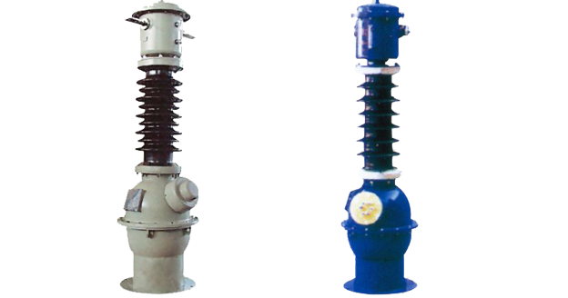
Product Shows
 Thomas Electric")
Working Principle
Operating on Faraday’s law of electromagnetic induction, the transformer features a toroidal magnetic core with primary conductor passing through the aperture and secondary windings wound around the core. The magnetic flux generated by primary current induces proportional voltage in the secondary winding, delivering standardized 5 A output current through connected burden. The oil-paper insulation system provides thermal dissipation and enhanced dielectric strength for outdoor medium-voltage applications.
System Application Position
- Medium Voltage Distribution: 35 kV switchgear, distribution substations, and outdoor line installations
- Energy Metering: Revenue-grade electricity measurement systems for utility and industrial applications
- Protection Circuits: Overcurrent, differential, and distance protection schemes in 35 kV networks
- SCADA Integration: Supervisory control and data acquisition systems for power distribution monitoring
Structural Form Overview
Oil-immersed construction with fully-sealed oil tank design ensures superior insulation performance, thermal stability, and long-term reliability in outdoor environments. The oil-paper insulation system undergoes vacuum drying and oil impregnation processes to eliminate moisture and ensure consistent dielectric properties. The external tank can be customized for material and dimensions based on installation requirements. The post-type mounting configuration provides stable mechanical support while maintaining required electrical clearances for 35 kV systems.
Model Designation
Model Code Explanation
 Thomas Electric")
LB6-35:
- L — Current transformer (CT)
- B — Protection configuration available (metering/protection application)
- 6 — Design series code
- 35 — Voltage class (kV)
LABN6-35:
- L — Current transformer (CT)
- A — Outdoor installation type
- B — Protection configuration available
- N — Internal structure identifier
- 6 — Design series code
- 35 — Voltage class (kV)
Variant Differences
LB6-35 and LABN6-35 are electrically equivalent when specified with the same ratio, accuracy classes, burdens, and Ith/Idyn ratings. The differences between the two models are primarily related to internal construction details and specific application requirements. Both models provide identical metering and protection performance when ordered with matching electrical specifications.
Service Conditions
The LB6-35 and LABN6-35 series current transformers are designed for outdoor operation under normal service conditions in medium-voltage power systems.
- Installation environment: Outdoor installation
- Altitude: ≤1000 m above sea level (higher altitude requires engineering confirmation and specification adjustment)
- Ambient temperature: −25 °C to +40 °C
- Pollution class: Grade II or Grade III as specified (corresponding creepage distance selection required)
- Environmental conditions: Suitable for outdoor environments with normal atmospheric conditions; free from corrosive gases, explosive media, or severe mechanical vibration
Construction
Construction Design
- Structure: Post-type support structure for outdoor installation
- Insulation: Fully-sealed oil-paper insulation system
- Core: Ring-type (toroidal) magnetic core design
- Oil tank: Fully-sealed tank construction, vacuum-dried and oil-impregnated
- Weatherproofing: External tank designed for long-term outdoor exposure with corrosion resistance
- Customization: Oil tank dimensions and materials customizable based on installation requirements
The oil-paper insulation provides stable dielectric properties, thermal dissipation, and resistance to moisture ingress. Vacuum drying and oil impregnation processes ensure elimination of internal moisture and air pockets, preventing oil degradation and insulation failure over the transformer’s service life.
Windings & Terminal Marking
- Primary terminals: P1 / P2
- Secondary terminals (Metering core): 1S1 / 1S2
- Secondary terminals (Protection core 1): 2S1 / 2S2
- Secondary terminals (Protection core 2): 3S1 / 3S2 (where applicable)
Terminal markings follow standard CT polarity conventions per IEC 61869-2 and GB/T 20840.2. Under normal operating conditions, the reference current direction is defined from P1 to P2. Correct terminal identification shall be observed to ensure metering accuracy and protection relay coordination.
Technical Data
This section provides selection-oriented technical data for the LB6-35 / LABN6-35 series outdoor, oil-immersed current transformer used in 35 kV class AC systems (50 Hz or 60 Hz). Data shown below is intended for preliminary selection of rated primary current, accuracy class combinations, rated burdens, and short-circuit withstand capability.
Definitions: Accuracy class combination indicates available metering/protection cores in one CT (multi-core configuration standard). Rated output (VA) is specified per secondary core. Ith is the rated short-time thermal current (1 s duration). Idyn is the rated dynamic current (peak value).
Notation: Ith is expressed in kA (1 s), Idyn is expressed in kA (peak). Acceptance shall be based on nameplate values and factory test report conformance to ordered specification.
Data Reference
| Rated Primary Current (A) |
Accuracy Class Combination |
Rated Output (VA) |
10P Class ALF |
Short-time Thermal Current Ith (kA, 1s) |
Rated Dynamic Current Idyn (kA, peak) |
|||
|---|---|---|---|---|---|---|---|---|
| 5 | 0.5/10P1/10P2 0.2/10P1/10P2 |
30 | 40 | 40 | 30 | 20 | 0.5 | 1.28 |
| 10 | 1 | 2.55 | ||||||
| 15 | 1.5 | 3.83 | ||||||
| 20 | 2 | 5.1 | ||||||
| 30 | 3 | 7.65 | ||||||
| 40 | 4 | 10.2 | ||||||
| 50 | 5 | 12.75 | ||||||
| 75 | 7.5 | 19.13 | ||||||
| 100 | 10 | 25.5 | ||||||
| 150 | 15 | 38.3 | ||||||
| 200 | 20 | 51 | ||||||
| 300 | 30 | 76.5 | ||||||
| 400~2000 | 40 | 102 | ||||||
Standards & Normative References
| Standard | Title | Application |
|---|---|---|
| IEC 61869-1 | Instrument Transformers – Part 1: General Requirements | General requirements |
| IEC 61869-2 | Instrument Transformers – Part 2: Additional Requirements for Current Transformers | CT-specific requirements |
| GB/T 20840.1 | Instrument Transformers – Part 1: General Requirements | National standard (aligned with IEC 61869 framework) |
| GB/T 20840.2 | Instrument Transformers – Part 2: Current Transformers | National CT requirements (aligned with IEC 61869-2) |
| GB 1208-1997 | Current Transformers | National CT standard where specified by the project |
| DL/T 866 | Technical Specifications for Current Transformers and Voltage Transformers | Power utility technical specifications (China) |
| IEEE C57.13 | Standard Requirements for Instrument Transformers | Optional (North America project reference) |
| IEC 60815 | Selection and Dimensioning of High-Voltage Insulators – Polluted Conditions | Creepage distance determination for pollution severity |
Factory Testing Compliance
- Routine tests per applicable IEC/GB requirements (including polarity/marking verification, ratio verification, and accuracy verification per specified class and burden)
- Dielectric tests per insulation coordination requirements (power frequency withstand voltage, lightning impulse withstand voltage per 40.5 / 95 / 185 kV)
- Partial discharge test where specified by project requirement
- Visual and dimensional inspection including marking, workmanship conformity, and creepage distance verification
- Oil quality tests (breakdown voltage, moisture content, and dielectric loss factor where applicable)
- Type and special tests as required by project specification
Installation & Dimensions
- Outline dimensions and mounting details are provided in the dimensional drawings.
- The transformer shall be securely mounted using the designated fixing holes on a stable foundation or support structure.
- Primary conductor connection may be made via busbar pass-through or bolted terminals, depending on the installation configuration.
- Adequate clearance shall be maintained for insulation coordination, heat dissipation, and maintenance access.
- Ensure compliance with minimum electrical clearances per applicable standard and local regulations.
Outlines & Physical Dimensions
| Rated Primary Current (A) |
Base Dimension B (mm) |
Height h (mm) |
Total Height H (mm) |
Oil Weight (kg) |
Total Weight (kg) |
|---|---|---|---|---|---|
| 5 – 75 | 508 | 1315 | 1475 | 25 | 160 |
| 100 – 600 | 508 | 1315 | 1475 | 25 | 160 |
| 750 – 1000 | 548 | 1315 | 1475 | 29 | 190 |
| 1200 – 1500 | 588 | 1315 | 1475 | 29 | 190 |
| 2000 | 658 | 1335 | 1495 | 32 | 205 |
Safety Notes
- Secondary circuit must never be left open when the transformer is energized, as dangerous high voltage may appear across the secondary terminals.
- During inspection or maintenance, the secondary circuit shall be short-circuited before disconnecting any instruments or protection relays.
- One point of the secondary circuit should be reliably grounded in accordance with applicable standards and local utility practice.
- All installation and maintenance work shall comply with local electrical safety regulations and substation operating procedures.
- Ensure oil level inspection and periodic maintenance per manufacturer recommendations and utility maintenance schedules.
Ordering Information
When placing an order, the required configuration shall be specified according to the local grid requirements, applicable standards, and project technical specification. The following parameters shall be clearly stated for technical confirmation and production release:
- Model selection: LB6-35 or LABN6-35
- Rated primary current / transformation ratio
- Rated secondary current: 5 A (standard)
- Application and accuracy requirements: Metering and/or protection accuracy class combination (e.g., 0.2 / 10P10 / 10P20)
- Rated burden (VA): For each secondary core/winding
- Short-circuit withstand requirements: Ith (1 s) and Idyn (peak) per system fault level
- Insulation level: Standard 40.5 / 95 / 185 kV or as required
- Pollution class: Grade II or Grade III (determines creepage distance requirement)
- Customization requirements: Tank dimensions, material specifications, or mounting configuration if applicable
How to select
- Determine rated primary current (Ip) based on feeder/load rating and expected operating range.
- Select metering and/or protection accuracy requirements (e.g., 0.2 or 0.5 for metering; 10P10 or 10P20 for protection).
- Confirm rated burden (VA) for each secondary circuit based on connected meters/relays and wiring losses.
- Verify short-circuit withstand capability (Ith/Idyn) against the system prospective fault current at installation point.
- Confirm insulation level and pollution class based on installation environment and local standards.
If local utility or project requirements apply (e.g., specific terminal arrangement, documentation language, required certificates, or special environmental conditions), specify them at the ordering stage. Special configurations shall be confirmed by technical agreement and final data sheet prior to production.