Product Overview
Functional Definition
The LKZB-0.5 (LBD-LCT) series split-core zero-sequence current transformers are precision electromagnetic protection devices designed for residual (zero-sequence) current detection and earth-fault protection in medium-voltage AC cable systems. Based on electromagnetic induction, the transformer monitors the vector sum of three-phase currents (zero-sequence component) to indicate insulation degradation, leakage, or ground fault conditions.
Key Ratings
| Item | Specification (per order / nameplate) |
|---|---|
| System voltage class | 6–35 kV class (cable head / termination cabinet applications) |
| Rated frequency | 50 Hz or 60 Hz |
| Rated secondary current | 1 A |
| Accuracy class | 10P10 (protection core) |
| Rated burden | 1–5 VA (per specification) |
| Burden power factor | cosφ = 0.8 (lagging) unless otherwise specified |
| Core aperture diameter | φ60 / φ80 / φ100 / φ150 / φ180 mm (custom up to 240 mm) |
| Insulation level | Secondary insulation 3 kV AC (1 min) — primary insulation provided by cable insulation system |
| Installation type | Split-core (opening) structure with bolt fastening |
| Applicable standards | IEC 61869-1 / IEC 61869-2; GB 1208-1997; DL/T 856-2004 (and other applicable project standards) |
| Certification | Qualified by Electric Power Automation Equipment Quality Inspection and Testing Center |
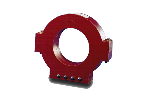
Product Shows
 split-core zero-sequence current transformers (6–35kV) Thomas Electric")
Working Principle
Operating on Faraday’s law of electromagnetic induction, the zero-sequence current transformer uses a toroidal magnetic core with all three-phase conductors passing through the center aperture. Under balanced three-phase conditions, the vector sum of currents is approximately zero and no effective magnetic flux is produced. During an earth fault or insulation breakdown, residual (zero-sequence) current generates magnetic flux in the core and induces a proportional secondary signal to drive protection relays and monitoring devices.
System Application Position
- Cable Ground Fault Protection: 6–35 kV power cable systems
- Relay Protection Systems: Zero-sequence overcurrent and earth-fault detection
- Grounding System Monitoring: Direct grounded, ungrounded, high-resistance grounded, low-resistance grounded, and arc-suppression coil grounded systems
- Industrial Power Distribution: Electric power, metallurgy, coal mining, railway, petroleum, chemical, and building materials industries
Structural Overview
Split-core construction with ABS engineering plastic housing and epoxy resin encapsulation provides stable insulation performance, moisture resistance, and mechanical strength. The opening mechanism enables installation without cable disconnection, supporting retrofit and maintenance work in cable termination cabinets. The two-piece design with bolt fastening ensures secure mechanical closure and consistent magnetic coupling for long-term protection operation.
Model Designation
 split-core zero-sequence current transformers (6–35kV) Thomas Electric")
Model Code Explanation
- L — Current transformer (CT)
- K — Protection application (zero-sequence protection)
- Z — Cast-resin (epoxy) insulated, enclosed structure
- B — Split-core (opening / clamp-on) construction
- 0.5 — Insulation class designation for secondary side (as specified)
- LBD-LCT — Series code indicating split-core zero-sequence protection transformer
Structural Variants
The LKZB-0.5 series is available in circular and rectangular (square) housing configurations to accommodate different cable installation environments and space constraints. Both variants provide equivalent electrical performance when specified with the same current ratio, accuracy class, burden, and aperture size. Selection between circular and rectangular housing is based on installation clearance, cable arrangement geometry, and cabinet layout.
Service Conditions
The LKZB-0.5 (LBD-LCT) series zero-sequence current transformers are designed for indoor operation under normal service conditions in medium-voltage cable systems.
- Installation environment: Indoor installation only (cable termination cabinets, distribution switchgear)
- Altitude: Not exceeding 1000 m above sea level (higher altitude shall be specified for engineering confirmation)
- Ambient temperature: −5 °C to +40 °C
- Relative humidity: Daily average ≤ 95%, monthly average ≤ 90% (at +20 °C reference)
- Environmental conditions: Free from corrosive gases or vapors; free from explosive or flammable media; no severe vibration, mechanical shock, or impact; suitable for normal indoor cable installation environments
Construction
Construction Design
- Structure: Split-core (opening / clamp-on) type for cable installation
- Housing: ABS engineering plastic with high mechanical strength and insulation properties
- Insulation: Epoxy resin encapsulation of magnetic core and secondary winding
- Core: Ring-type (toroidal) magnetic core optimized for residual current detection
- Closure mechanism: Two-piece construction with bolt fastening for secure closure
- Mounting: Two fixing holes in base for secure installation
The epoxy resin encapsulation provides stable insulation properties and resistance to moisture, contamination, and aging for long-term indoor service. The split-core structure avoids cable disconnection during installation or replacement.
Core Aperture Specifications
Standard aperture diameters: φ60 mm, φ80 mm, φ100 mm, φ150 mm, φ180 mm. Custom aperture sizes up to φ240 mm are available upon request. The selected aperture must accommodate all three-phase conductors with adequate clearance for cable insulation and installation tolerances.
Windings & Terminal Marking
- Primary: Cable conductors passing through center aperture (no galvanic connection)
- Secondary terminals: K1 / K2
Terminal markings follow standard zero-sequence CT conventions. Under balanced three-phase conditions, residual current is negligible. During earth-fault conditions, secondary terminals K1 and K2 deliver output to the protection relay. Correct polarity shall be observed to ensure proper protection directionality and coordination.
Technical Data
This section provides selection-oriented technical data for the LKZB-0.5 (LBD-LCT) series indoor split-core zero-sequence current transformer used in 6–35 kV class AC cable systems (50 Hz or 60 Hz). The data supports preliminary selection of current ratio, accuracy class, and rated burden based on protection relay requirements and grounding practice.
Definitions: Accuracy class 10P10 indicates protection-class accuracy with composite error within specified limits up to 10× rated primary current (accuracy limit factor ALF = 10). Rated output (VA) is the allowable burden at rated secondary current. The transformer measures zero-sequence (residual) current, i.e., the vector sum of three-phase currents during earth faults.
Notation: Current ratio reflects the expected residual current detection range with a 1 A secondary output. Selection shall consider maximum earth-fault current, relay pickup sensitivity, and cable system grounding configuration.
Data Reference
| Rated Primary Current (A) |
Accuracy Class | Rated Output (VA) |
Aperture Diameter Options |
|---|---|---|---|
| 50 | 10P10 | 1 | φ60 / φ80 / φ100 / φ150 / φ180 |
| 75 | 10P10 | 1.6 | φ60 / φ80 / φ100 / φ150 / φ180 |
| 100 | 10P10 | 2.5 | φ60 / φ80 / φ100 / φ150 / φ180 |
| 150 | 10P10 | 5 | φ60 / φ80 / φ100 / φ150 / φ180 |
| 200 | 10P10 | 5 | φ60 / φ80 / φ100 / φ150 / φ180 |
| 300 | 10P10 | 5 | φ60 / φ80 / φ100 / φ150 / φ180 |
| 400 | 10P10 | 5 | φ60 / φ80 / φ100 / φ150 / φ180 |
| 600 | 10P10 | 5 | φ60 / φ80 / φ100 / φ150 / φ180 |
Standards & Normative References
| Standard | Title | Application |
|---|---|---|
| IEC 61869-1 | Instrument Transformers – Part 1: General Requirements | General requirements for instrument transformers |
| IEC 61869-2 | Instrument Transformers – Part 2: Additional Requirements for Current Transformers | CT-specific technical requirements |
| GB 1208-1997 | Current Transformers | National CT standard where specified by project |
| DL/T 856-2004 | Technical Specification for Protection CT and Voltage Transformer | Protection transformer requirements for power systems |
| GB/T 16927.1 | High-voltage Test Techniques – Part 1: General Definitions and Test Requirements | Dielectric testing requirements |
| IEEE C37.60 | Requirements for Automatic Circuit Reclosers | Optional (protection system integration reference) |
Factory Test Compliance
- Routine tests per applicable IEC/GB requirements (polarity/marking verification, ratio check, and protection accuracy verification at specified burden)
- Dielectric tests — Secondary insulation withstand: 3 kV AC for 1 minute (primary insulation provided by cable insulation system)
- Accuracy verification at rated burden and at accuracy limit factor (10 × In)
- Visual and dimensional inspection including marking, aperture clearance, and split-core closure mechanism operation
- Type and special tests as required by project specification or certification authority
Installation & Dimensions
- The split-core construction permits installation on existing cable without cable disconnection.
- Position the two halves around the cable bundle with all three-phase conductors passing through the aperture.
- Maintain adequate clearance between cable insulation and aperture walls.
- Join and secure the two halves using the supplied bolts with specified torque.
- Mount the transformer using the two fixing holes to prevent vibration or movement.
- Route secondary wiring to the protection relay with proper mechanical support and strain relief.
Dimensional Data
| Model | Aperture Diameter φ (mm) |
Width L (mm) |
Height H (mm) |
Thickness (mm) |
Mounting Hole Specification |
Mounting Hole Center Distance |
|---|---|---|---|---|---|---|
| LCT-2 | 80 | 210 | 200 | 55 | M × 25 | 110 ± 0.5 |
| LCT-3 | 100 | 260 | 230 | 55 | M × 25 | 110 ± 0.5 |
| LCT-4 | 120 | 260 | 230 | 55 | M × 25 | 110 ± 0.5 |
Outline Drawing
 split-core zero-sequence current transformers (6–35kV) Thomas Electric")
Safety Notes
- Secondary circuit must never be left open when the cable system is energized, as dangerous high voltage may appear across secondary terminals during fault conditions.
- During inspection or maintenance, short-circuit the secondary circuit before disconnecting relays or instruments.
- One point of the secondary circuit should be reliably grounded in accordance with applicable standards and local practice.
- Fasten the split-core closure mechanism with specified bolt torque to ensure consistent performance.
- All installation and maintenance work shall comply with local electrical safety regulations and cable system operating procedures.
- Verify polarity and terminal connections before energizing protection circuits.
Ordering Information
When placing an order, specify the configuration according to cable system parameters, grounding method, relay requirements, and project specification. The following parameters shall be stated for technical confirmation and production release:
- Rated primary current / ratio (e.g., 100/1, 200/1)
- Rated secondary current (1 A standard)
- Accuracy class (10P10 for protection)
- Rated burden (VA) based on relay input impedance and wiring resistance
- Core aperture diameter (φ60 / φ80 / φ100 / φ150 / φ180 or custom)
- Housing configuration (circular or rectangular/square)
Selection Guidance: Select rated primary current based on maximum expected residual earth-fault current. Confirm that the ratio meets relay sensitivity requirements for high-impedance faults while avoiding saturation at maximum fault current. Verify rated burden (VA) covers relay impedance plus secondary wiring resistance along the full run. Select aperture size to accommodate three-phase conductors with adequate clearance and tolerances. If specific utility/project requirements apply (verification points, terminal arrangement, mounting constraints, documentation language, certificates), state them at ordering for technical agreement and final datasheet confirmation.