Product Overview
Functional Definition
The LCWD1-35 (LABN1-35W2) 35kV outdoor oil-immersed current transformers, are precision electromagnetic instruments designed for accurate current measurement, energy metering, and relay protection applications in 35 kV class AC power systems. These oil-immersed outdoor current transformers utilize electromagnetic induction principles to provide galvanically isolated secondary current signals proportional to primary current, operating at 50 Hz or 60 Hz.
Key Ratings Snapshot
| Item | Specification (per order / nameplate) |
|---|---|
| System voltage class | 35 kV class (outdoor distribution and transmission applications) |
| Rated frequency | 50 Hz / 60 Hz |
| Rated secondary current | 5 A |
| Accuracy classes | Metering and/or protection cores as specified (e.g., 0.2S, 0.5, 10P15, 10P20) |
| Rated burden | Per core/winding as specified: 0.2S (30 VA), 0.5 (50 VA), 10P20 (50 VA) |
| Burden power factor | cosφ = 0.8 (lagging) unless otherwise specified by the project standard |
| Short-circuit withstand | Ith (1 s) and Idyn (peak) as specified per primary current rating |
| Insulation level | 40.5/95/185 kV (Um/Up/Ud) |
| Creepage distance | Standard: ≥735 mm; W2 variant: ≥1100 mm |
| Pollution class | Class II or Class III (selectable) |
| Applicable standards | IEC 61869-1 / IEC 61869-2; GB/T 20840.1 / 20840.2; GB 1208-1997; GB 5583-85 (PD where specified) |
| Structural variants | LCWD1-35 (standard), LABN1-35W2 (extended creepage) |
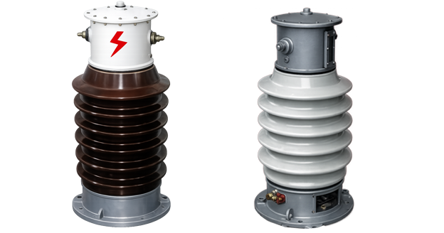
Product Show

Working Principle
Operating on Faraday’s law of electromagnetic induction, the transformer features a toroidal magnetic core with primary conductor passing through the aperture and secondary windings wound around the core. The magnetic flux generated by primary current induces proportional voltage in the secondary winding, delivering standardized 5 A output current through connected burden. The oil-immersed construction provides enhanced insulation capability and thermal performance for outdoor operation.
System Application Position
- Medium-High Voltage Distribution: 35 kV outdoor substations and distribution systems
- Energy Metering: Revenue-grade electricity measurement systems
- Protection Circuits: Overcurrent, differential, and distance protection schemes
- SCADA Integration: Supervisory control and data acquisition systems
Structural Overview
Oil-immersed construction with porcelain bushing insulation ensures superior insulation performance, moisture resistance, and outdoor weatherability. The compact design undergoes vacuum drying and oil filling processes to achieve high dielectric strength. The porcelain bushing is mounted on a metallic base, with an oil conservator (expansion tank) at the top equipped with oil level and temperature indicators for maintenance monitoring.
Model Designation
Model Code Explanation
- L — Current transformer (CT)
- C — Outdoor installation type
- W — Oil-immersed construction
- D — Single-phase configuration
- 1 — Design code (platform/iteration)
- 35 — Voltage class (kV)
- W2 — Extended creepage distance variant (when specified)
Variant Differences
LCWD1-35 and LABN1-35W2 are electrically equivalent when specified with the same ratio, accuracy classes, burdens, and Ith/Idyn. The W2 variant provides extended creepage distance (≥1100 mm vs ≥735 mm standard) for higher pollution environments (Class III vs Class II). Selection between variants is based on site pollution level requirements and environmental conditions.
Service Conditions
The LCWD1-35 series current transformers are designed for outdoor operation under normal service conditions in 35 kV power systems.
- Installation environment: Outdoor installation
- Altitude: ≤1000 m (higher altitude shall be specified for engineering confirmation)
- Ambient temperature: −25 °C to +40 °C
- Relative humidity: Daily average ≤ 95%, monthly average ≤ 90%
- Pollution class: Class II (standard) or Class III (W2 variant)
- Environmental conditions: Suitable for outdoor exposure; no severe mechanical shock or vibration
Construction
Construction Design
- Structure: Post-type for outdoor substations
- Insulation: Oil-immersed with porcelain bushing insulation
- Core: Ring-type magnetic core design
- Processing: Vacuum drying and oil filling for optimal insulation
- Oil conservator: Top-mounted expansion tank with oil level and temperature indicators
The oil-immersed construction with vacuum-dried core assembly provides stable insulation properties and resistance to moisture, contamination, and aging for long-term outdoor service. The porcelain bushing provides robust mechanical protection and electrical insulation.
Windings & Terminal Marking
- Primary winding: Located in upper section of core assembly
- Secondary winding: Located in lower section of core assembly
- Terminal arrangement: P1 terminal insulated through small porcelain bushing (isolated from enclosure); P2 terminal connects directly to metallic base for grounding
Terminal Marking
- Primary terminals: P1 / P2
- Secondary terminals (Group 1): 1S1 / 1S2
- Secondary terminals (Group 2): 2S1 / 2S2 (when dual-core configuration)
Terminal markings follow standard CT polarity conventions per IEC 61869-2. Under normal operating conditions, the reference current direction is defined from P1 to P2. Correct terminal identification shall be observed to ensure metering and protection performance.
Technical Data
This section provides selection-oriented technical data for the LCWD1-35 / LABN1-35W2 series outdoor, oil-immersed current transformer used in 35 kV class AC systems (50 Hz / 60 Hz). Data shown below is intended for preliminary selection of accuracy class combinations, rated burdens, and short-circuit withstand capability.
Definitions: Accuracy class combination indicates available metering/protection cores in one CT (multi-core configuration may apply). Rated output (VA) is specified per secondary core. Ith is the rated short-time thermal current (1 s). Idyn is the rated dynamic current (peak).
Notation: Ith/Idyn values are specified for each primary current rating and verified by factory test. Acceptance shall be based on nameplate values and the factory test report.
Data Reference
| Rated Primary Current (A) |
Accuracy Class Combination |
Rated Output 0.2S (VA) |
Rated Output 0.5 (VA) |
Rated Output 10P20 (VA) |
Thermal Current Ith (kA/1s) |
Dynamic Current Idyn (kA) |
|---|---|---|---|---|---|---|
| 5 | 0.5/10P15
0.2/0.5 0.2/0.2 |
30 | 50 | 50 | 0.375 | 0.95 |
| 10 | 0.75 | 1.9 | ||||
| 15 | 1.12 | 2.9 | ||||
| 20 | 1.5 | 3.8 | ||||
| 30 | 2.25 | 5.7 | ||||
| 40 | 3 | 7.6 | ||||
| 50 | 3.75 | 9.6 | ||||
| 75 | 5.62 | 14.5 | ||||
| 100 | 7.5 | 19.2 | ||||
| 200 | 11.25 | 28.7 | ||||
| 300 | 15 | 38.3 | ||||
| 400 | 22.5 | 57.5 | ||||
| 600 | 30 | 76.5 | ||||
| 800 | 45 | 115 | ||||
| 1000 | 45 | 115 | ||||
| 1200 | 45 | 115 | ||||
| 1500 | 45 | 115 |
10P level accuracy limit factor

For 10P class protection cores, the accuracy limit factor (ALF) is specified in the accuracy class designation (e.g., 10P15 indicates ALF = 15, 10P20 indicates ALF = 20). This factor defines the ratio of rated accuracy limit primary current to rated primary current at which the composite error does not exceed 10%.
Standards & Normative References
| Standard | Title | Application |
|---|---|---|
| IEC 61869-1 | Instrument Transformers – Part 1: General Requirements | General requirements |
| IEC 61869-2 | Instrument Transformers – Part 2: Additional Requirements for Current Transformers | CT-specific requirements |
| GB/T 20840.1 | Instrument Transformers – Part 1: General Requirements | National standard (aligned with IEC 61869 framework) |
| GB/T 20840.2 | Instrument Transformers – Part 2: Current Transformers | National CT requirements (aligned with IEC 61869-2) |
| GB 1208-1997 | Current Transformers | National CT standard where specified by the project |
| GB 5583-85 | Partial Discharge Level Requirements | Partial discharge requirements where specified by the project |
| IEEE C57.13 | Standard Requirements for Instrument Transformers | Optional (North America project reference) |
| IEC 60068-2-17 | Environmental Testing – Salt Mist | Optional (project-specific environmental validation) |
| IEC 60085 | Electrical Insulation – Thermal Evaluation | Optional (insulation thermal evaluation reference) |
Factory Test Compliance
- Routine tests per applicable IEC/GB requirements (including polarity/marking, ratio verification, and accuracy verification per specified class and burden)
- Dielectric tests per insulation coordination requirements and applicable standard (40.5/95/185 kV)
- Partial discharge test where specified by the project requirement (GB 5583-85)
- Visual and dimensional inspection including marking and workmanship conformity
- Type and special tests as required by the project specification
Installation & Dimensions
Outline


- Outline dimensions and mounting details are provided in the dimensional drawings.
- The transformer shall be securely mounted using the designated fixing holes on the metallic base.
- Primary conductor connection may be made via busbar or threaded stud terminals, depending on primary current rating.
- Adequate clearance shall be maintained for insulation, heat dissipation, and maintenance access.
- Oil level and temperature indicators on the conservator shall be accessible for routine inspection.
connection size
Screw-type connection size
| Primary Current Range (A) | Connection Type | Thread Size |
|---|---|---|
| 5 – 500 | Threaded stud | M22 × 1.5 |
| 600 – 1000 | Threaded stud | M27 × 1.5 |
| 1200 – 1500 | Threaded stud | M30 × 1.5 |
Copper busbar connection size
| Primary Current Range (A) | B Dimension (mm) |
|---|---|
| 5 – 500 | 410 |
| 600 – 1000 | 440 |
| 1200 – 1500 | 440 |
Safety Notes
- Secondary circuit must never be left open when the transformer is energized, as dangerous high voltage may appear across the secondary terminals.
- During inspection or maintenance, the secondary circuit shall be short-circuited before disconnecting any instruments.
- One point of the secondary circuit should be reliably grounded in accordance with applicable standards.
- All installation and maintenance work shall comply with local electrical safety regulations.
- Oil level shall be checked regularly; replenish with matching transformer oil if level drops below minimum mark.
- Temperature indicators shall be monitored; excessive temperature may indicate overload or internal fault.
Ordering Information
When placing an order, the required configuration shall be specified according to the local grid requirements, applicable standards, and project technical specification. The following parameters shall be clearly stated for technical confirmation and production release:
- Rated primary current / transformation ratio
- Rated secondary current (5 A standard)
- Application and accuracy requirements (metering and/or protection accuracy class combination)
- Rated burden (VA) for each secondary core/winding
- Short-circuit withstand requirements: Ith (1 s) and Idyn (peak)
- Insulation level: 40.5/95/185 kV (standard) or custom
- Pollution class: Class II (standard, ≥735 mm creepage) or Class III (W2, ≥1100 mm creepage)
- Primary connection type: Threaded stud or busbar connection
- Custom requirements: Oil tank structure, materials, dimensions, mounting configuration
How to select
1: Determine rated primary current (Ip) based on feeder/load rating and expected operating range for 35 kV system.
2: Select metering and/or protection accuracy requirements (e.g., 0.2S for precision metering; 0.5 for general metering; 10P15 or 10P20 for protection).
3: Confirm rated burden (VA) for each secondary circuit based on connected meters/relays and wiring losses.
4: Verify short-circuit withstand capability (Ith/Idyn) against the substation fault level.
5: Select pollution class based on site environmental assessment (Class II standard or Class III for heavy pollution areas).
If local utility or project requirements apply (e.g., specific insulation coordination, partial discharge limits, terminal arrangement, mounting constraints, oil tank customization, documentation language, or required certificates), specify them at the ordering stage. Special configurations shall be confirmed by technical agreement and final data sheet prior to production.
FAQs