Product Overview
Functional Definition
The LJ-2, LJ-4, and LJ-7 series zero-sequence current transformers are indoor-type electromagnetic devices designed for residual (zero-sequence) current detection in low-current grounding systems. They are commonly applied for ground fault protection of generators, synchronous condensers, and motors, and are typically used in conjunction with DD-11/60 relays to form a complete ground fault protection scheme.
During normal three-phase operation, the vector sum of phase currents passing through the core window is approximately zero and the secondary output is minimal. When a ground fault occurs within the protection zone, the residual current produces net magnetic flux in the toroidal core, inducing a secondary current signal that drives relay operation for fault indication or tripping.Key Ratings

| Item | Specification |
|---|---|
| Application | Residual (zero-sequence) current detection for ground fault protection in low-current grounding systems |
| Installation environment | Indoor installation only |
| Typical system scope | AC 50/60 Hz systems, commonly applied in ≤35 kV class networks (project-dependent) |
| Protected equipment | Generators, synchronous condensers, motors, and cable feeders (residual current protection) |
| Typical relay pairing | DD-11/60 ground fault relay (or equivalent residual-current relay per project design) |
| Primary insulation | Provided by the passing cable insulation; the transformer is typically assessed for secondary winding insulation performance only |
| Secondary winding insulation | 3 kV power frequency withstand voltage to ground (1 min) |
| Supported cable outside diameter | ≤ 50 mm (for larger diameters, select a larger-window model) |
Working Principle
Zero-sequence current transformers operate on electromagnetic induction. All phase conductors of the protected circuit (and neutral where required by the protection scheme) pass through the CT window. Under balanced conditions, the resultant magnetic flux is near zero. Under ground fault conditions, residual current produces net flux in the toroidal core and induces a secondary current proportional to the residual component, enabling sensitive ground fault detection by connected relays.
System Application Position
- Generator Protection: Ground fault protection for generator stator or feeder circuits
- Motor Protection: Ground fault detection for medium and large motors
- Synchronous Condenser Protection: Residual current monitoring in reactive power compensation equipment
- Cable Feeder Protection: Residual current detection on multi-core or parallel cable feeders
Structural Overview
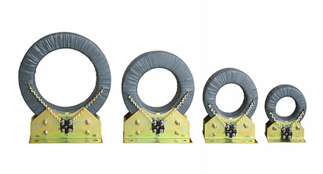
The LJ series adopts a ring-type (toroidal) magnetic core to provide uniform flux distribution and high sensitivity. The secondary winding is evenly distributed to ensure stable output characteristics. A mounting bracket with pre-positioned fixing holes supports fast installation and reliable mechanical fixation in indoor panels, switchgear rooms, or cable trenches.
Model Designation

Model Code Explanation
- L — Current transformer (CT)
- J — Zero-sequence / ground fault protection application
- 2 / 4 / 7 — Number of cables supported (typical application reference)
Model Variants
The LJ series provides three standard variants based on cable capacity and window size:
- LJ-2: For 1–2 cables; typical ratio 20/1
- LJ-4: For 3–4 cables; typical ratio 20/1
- LJ-7: For 5–7 cables; typical ratio 40/1
Service Conditions
The LJ series zero-sequence current transformers are designed for indoor operation under normal service conditions.
- Installation environment: Indoor installation only
- Rated frequency: 50 Hz or 60 Hz
- Altitude: Not exceeding 1000 m above sea level (higher altitude requires engineering confirmation)
- Ambient temperature: −5 °C to +40 °C
- Relative humidity: High-humidity indoor environments are acceptable provided no condensation occurs on live parts
- Environmental conditions: Free from corrosive gases, explosive or flammable media, severe vibration, mechanical shock, or impact
Construction
Construction Design
- Structure: Ring-type toroidal core design
- Core: High-permeability magnetic material for sensitivity
- Winding: Secondary winding uniformly distributed on core
- Mounting: Bracket with pre-positioned installation holes
- Insulation: Primary insulation by cable jacket; secondary winding withstands 3 kV power frequency to ground
Windings & Terminal Marking
- Primary circuit: Phase conductors passing through core aperture (no electrical primary terminals)
- Secondary terminals: Marked for connection to residual-current relay input
Observe the secondary terminal markings and polarity requirements to ensure correct relay operation and stable protection performance.
Technical Data
This section provides commonly used technical parameters for LJ-2, LJ-4, and LJ-7 zero-sequence current transformers used with residual-current relays. Final values shall follow the nameplate and factory test report for the specific order.
Electrical Parameters (Relay-Oriented)
| Model | Cable Capacity |
Secondary Loop Resistance (Ω) |
Adjustment / Setting Current (A) |
Sensitivity (A) |
Typical Rated Ratio (A) |
|---|---|---|---|---|---|
| LJ-2 | 1–2 | 10 | 0.03 | 1–3 | 20/1 |
| LJ-4 | 3–4 | 10 | 0.03 | 1–3 | 20/1 |
| LJ-7 | 5–7 | 10 | 0.03 | 1–3 | 40/1 |
Dimensional Data
| Model | A (mm) | B (mm) | H (mm) | ΦD (mm) | Φd (mm) |
|---|---|---|---|---|---|
| LJ-2 | 150 | 200 | 295 | 230 | 110 |
| LJ-4 | 220 | 280 | 335 | 285 | 140 |
| LJ-7 | 220 | 300 | 375 | 300 | 180 |
Standards & Normative References
| Standard | Title | Application |
|---|---|---|
| IEC 61869-1 | Instrument Transformers – Part 1: General Requirements | General requirements |
| IEC 61869-2 | Instrument Transformers – Part 2: Additional Requirements for Current Transformers | CT requirements (replaces IEC 60044-1) |
| GB 1208-2006 | Current Transformers | National CT standard (where specified by project) |
| GB/T 20840.1 | Instrument Transformers – Part 1: General Requirements | National standard aligned with IEC 61869-1 |
| GB/T 20840.2 | Instrument Transformers – Part 2: Current Transformers | National standard aligned with IEC 61869-2 |
Factory Test Compliance
- Routine tests per applicable standards including marking verification and basic electrical checks
- Secondary insulation test (power frequency withstand to ground) as specified
- Visual and dimensional inspection including workmanship and mounting integrity
- Type and special tests as required by project specification
Installation & Dimensions

- Use the mounting bracket fixing holes for secure installation on stable structures.
- Route all phase conductors of the protected circuit through the CT window; keep conductor layout compact and avoid unnecessary separation inside the window.
- For parallel cables per phase, ensure all parallel conductors pass through the same CT window to avoid false residual current.
- Route secondary wiring to the relay with clear identification and mechanical protection.
Ordering Information
When placing an order, specify the following parameters according to system requirements and project specifications:
- Model selection: LJ-2, LJ-4, or LJ-7 based on number of cables and window size
- Number of cables / conductor arrangement: including parallel cable configuration per phase
- Maximum cable outside diameter: confirm ≤50 mm or specify larger window requirement
- Relay type: e.g., DD-11/60 or equivalent residual-current relay input requirement
- Installation environment: indoor temperature, humidity, altitude, and mounting constraints
- Special requirements: documentation language, certificates, marking, or project-specific tests
How to Select: (1) Confirm how many cables must pass through the CT window and their maximum OD; (2) Select LJ-2 (1–2 cables), LJ-4 (3–4 cables), or LJ-7 (5–7 cables); (3) Confirm relay input requirements and secondary loop conditions; (4) Verify secondary insulation requirement (3 kV/1 min to ground typical); (5) Confirm installation constraints and documentation requirements before production release.