Product Overview
Functional Definition
The LJ-ZW-10(12) Zero-Sequence Current Transformers are precision electromagnetic instruments designed for ground fault detection, residual current measurement, and zero-sequence protection applications in medium-voltage AC power distribution systems. These outdoor-rated transformers utilize electromagnetic induction principles with specialized zero-sequence current sensing to provide galvanically isolated secondary current signals proportional to the vector sum of three-phase primary currents, enabling sensitive ground fault protection.
Key Ratings
| Item | Specification (per order / nameplate) |
|---|---|
| System voltage class | 10 kV / 12 kV class (outdoor distribution applications) |
| Rated frequency | 50 Hz (60 Hz available upon request) |
| Rated secondary current | 1 A |
| Accuracy classes | Protection core: 10P10 |
| Rated output | 0.1 Ω or 0.2 Ω (resistance output) |
| Primary current ratings | 20 A, 50 A (zero-sequence measurement) |
| Zero-sequence application | Ground fault detection and residual current protection |
| Insulation level | 10(12)/42 kV |
| Installation environment | Outdoor (IP-rated enclosure) |
| Applicable standards | IEC 61869-1 / IEC 61869-2; GB/T 20840.1 / 20840.2; GB 1208-1997 |
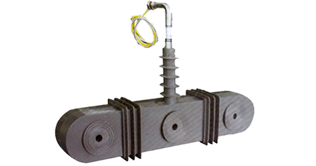
Product Shows
 Zero-Sequence Current Transformer epoxy-silicone outdoor Thomas Electric")
Working Principle
Operating on Faraday’s law of electromagnetic induction with zero-sequence current sensing topology, the transformer features a toroidal magnetic core through which all three-phase conductors pass simultaneously. Under balanced three-phase conditions, the vector sum of phase currents is zero, producing no net magnetic flux. During ground faults or unbalanced conditions, the residual current (I₀ = Ia + Ib + Ic) generates proportional magnetic flux in the core, inducing voltage in the secondary winding and delivering standardized output current through connected protection relays.
System Application Position
- Medium Voltage Distribution: 10kV-12kV outdoor switchgear and distribution networks
- Ground Fault Protection: Earth leakage detection and residual current protection schemes
- Zero-Sequence Protection: Directional ground overcurrent and sensitive earth fault protection
- Cable Feeder Monitoring: Cable system ground fault surveillance
- SCADA Integration: Remote monitoring of ground fault current
Structural Overview
Epoxy resin cast core construction with outdoor-rated silicone rubber housing ensures superior insulation performance, moisture resistance, UV stability, and mechanical strength under harsh environmental conditions. The toroidal aperture configuration accommodates three-phase cable or busbar assemblies while maintaining excellent electrical clearance and creepage distances. The fully-sealed outdoor enclosure meets IP-rated protection requirements for operation in contaminated and high-humidity environments.
Model Designation
Model Code Explanation
- L — Current transformer (CT)
- J — Zero-sequence (residual current) measurement configuration
- Z — Cast-resin (epoxy) insulated core
- W — Outdoor installation rated (weatherproof)
- 10(12) — Voltage class: 10 kV or 12 kV
Zero-Sequence Configuration
The LJ-ZW series employs a single toroidal core through which all three-phase conductors pass simultaneously. This topology measures the vector sum of three-phase currents (residual current I₀), making it specifically suited for ground fault detection where phase-to-ground fault currents must be isolated from normal load currents. The zero-sequence CT does not require individual phase-current measurement and is optimized for sensitive ground fault protection applications.
Service Conditions
The LJ-ZW-10(12) series zero-sequence current transformers are designed for outdoor operation under the following service conditions in medium-voltage power distribution systems:
- Installation environment: Outdoor installation with IP-rated enclosure
- Altitude: Not exceeding 2000 m above sea level (higher altitude configurations available upon specification)
- Ambient temperature: −25 °C to +40 °C
- Relative humidity: Daily average ≤ 95%, monthly average ≤ 90% (outdoor humidity cycling)
- Pollution level: Class II per IEC 60815 (suitable for light industrial and agricultural environments)
- Environmental conditions: Resistant to UV radiation, rain, ice, and moderate industrial contamination; free from explosive or flammable atmospheres
Construction
Construction Design
- Structure: Toroidal (ring-type) core with cable/busbar aperture for three-phase conductors
- Core insulation: Epoxy resin cast construction for moisture resistance and mechanical strength
- External housing: Silicone rubber enclosure for outdoor UV and weathering resistance
- Core material: High-permeability magnetic material optimized for zero-sequence sensitivity
- Sealing: Fully-sealed IP-rated design for outdoor environmental protection
The dual-layer insulation system combines epoxy resin cast core for electrical insulation with silicone rubber outer housing for environmental protection, providing long-term outdoor service life with minimal maintenance requirements. The toroidal geometry ensures uniform magnetic field distribution and high sensitivity to residual current detection.
Windings & Terminal Marking
- Primary conductors: Three-phase cables or busbars passing through toroidal aperture (no fixed terminals)
- Secondary terminals: S1 / S2 (zero-sequence output)
Terminal markings follow standard zero-sequence CT polarity conventions. Under ground fault conditions with positive residual current flow through the aperture, the secondary current flows from S1 to S2 into the connected burden. Correct polarity observation is critical for directional ground fault protection schemes.
Technical Data
This section provides selection-oriented technical data for the LJ-ZW-10(12) series outdoor zero-sequence current transformer used in 10 kV / 12 kV class AC distribution systems (50 Hz). Data shown below is intended for preliminary selection of primary current ratings, accuracy class, and output resistance.
Definitions: Primary current rating indicates the nominal zero-sequence current measurement range. Rated output (Ω) is the secondary winding resistance specification. Accuracy class 10P10 indicates protection-grade accuracy with 10% composite error at 10× rated primary current.
Notation: Zero-sequence CTs measure residual current (I₀ = Ia + Ib + Ic); under balanced three-phase conditions, secondary output is zero. Selection shall be based on anticipated ground fault current magnitude and protection relay sensitivity requirements.
Data Reference
| Model | Rated Primary Current (A) |
Rated Secondary Current (A) |
Accuracy Class |
Rated Output (Ω) |
Rated Insulation Level (kV) |
|---|---|---|---|---|---|
| LJ-ZW-10(12) | 20 | 1 | 10P10 | 0.1 | 10(12)/42 |
| LJ-ZW-10(12) | 50 | 1 | 10P10 | 0.2 | 10(12)/42 |
Standards & Normative References
| Standard | Title | Application |
|---|---|---|
| IEC 61869-1 | Instrument Transformers – Part 1: General Requirements | General requirements |
| IEC 61869-2 | Instrument Transformers – Part 2: Additional Requirements for Current Transformers | CT-specific requirements |
| GB/T 20840.1 | Instrument Transformers – Part 1: General Requirements | National standard (aligned with IEC 61869 framework) |
| GB/T 20840.2 | Instrument Transformers – Part 2: Current Transformers | National CT requirements (aligned with IEC 61869-2) |
| GB 1208-1997 | Current Transformers | National CT standard where specified by the project |
| IEC 60815 | Selection and Dimensioning of High-Voltage Insulators – Part 1: Definitions, Information and General Principles | Outdoor insulation and pollution class requirements |
| IEC 60529 | Degrees of Protection Provided by Enclosures (IP Code) | Outdoor enclosure protection rating |
Factory Test Compliance
- Routine tests per applicable IEC/GB requirements (including polarity/marking, ratio verification at rated current, and accuracy verification per 10P10 class)
- Dielectric tests per insulation coordination requirements (power-frequency withstand voltage and impulse voltage tests)
- Zero-sequence sensitivity verification to confirm detection capability at specified ground fault current levels
- Environmental tests where specified (temperature cycling, humidity resistance, UV aging)
- Visual and dimensional inspection including aperture sizing, marking conformity, and housing integrity
- Type and special tests as required by the project specification
Installation & Dimensions
- The transformer shall be mounted on outdoor switchgear or cable termination structures using the designated fixing arrangement.
- All three-phase conductors (cables or busbars) shall pass through the central aperture in the same direction to ensure correct zero-sequence current measurement.
- The toroidal aperture diameter shall accommodate the cable or busbar bundle with adequate clearance (minimum 10mm radial clearance recommended).
- Adequate creepage and clearance distances shall be maintained per IEC 60815 for the specified pollution class.
- Secondary wiring connections shall be made via the terminal compartment with proper gland sealing to maintain IP rating.
Outlines
 Zero-Sequence Current Transformer epoxy-silicone outdoor Thomas Electric")
Safety Notes
- Secondary circuit must never be left open when primary conductors are energized, as dangerous high voltage may appear across the secondary terminals.
- During inspection or maintenance, the secondary circuit shall be short-circuited before disconnecting any protection relays.
- One point of the secondary circuit should be reliably grounded in accordance with applicable standards.
- All three-phase conductors must pass through the aperture in the correct direction for proper zero-sequence polarity.
- All installation and maintenance work shall comply with local electrical safety regulations and utility standards.
Ordering Information
When placing an order, the required configuration shall be specified according to the local grid requirements, applicable standards, and project technical specification. The following parameters shall be clearly stated for technical confirmation and production release:
- Rated primary current (20 A or 50 A zero-sequence rating)
- Rated secondary current (1 A standard)
- Accuracy class (10P10 protection grade standard)
- Rated output resistance (0.1 Ω or 0.2 Ω)
- Insulation voltage class (10 kV or 12 kV)
- Cable/busbar aperture diameter requirement
- Pollution class (if Class III or IV required)
- IP rating requirement (if higher than standard)
How to Select
1: Determine anticipated maximum ground fault current based on system grounding method (solid, resistance, reactance, or isolated neutral) and feeder cable capacitance.
2: Select rated primary current (20 A or 50 A) to provide adequate measurement range while maintaining sensitivity for low-magnitude ground faults (typically 10-20% of rating).
3: Confirm rated output resistance (0.1 Ω or 0.2 Ω) based on connected protection relay input impedance and wiring resistance.
4: Verify aperture diameter accommodates cable bundle or busbar assembly with required clearance (specify conductor configuration and dimensions).
5: Specify pollution class per IEC 60815 if installation site exceeds Class II conditions (coastal, heavy industrial, desert environments may require Class III or IV).
If local utility or project requirements apply (e.g., enhanced IP rating, terminal arrangement, documentation language, or required certificates), specify them at the ordering stage. Special configurations shall be confirmed by technical agreement and final data sheet prior to production.