Product Overview
Functional Definition
The LJ‑ZW3/ZW43‑10(12) zero‑sequence protection current transformers are engineered for accurate three‑phase current measurement, energy metering, and relay protection in 10 kV and 12 kV AC distribution systems at 50 Hz. These units integrate three‑phase measurement with zero‑sequence fault detection and are designed for use with ZW2 and ZW43 series vacuum circuit breakers. They provide galvanically isolated secondary outputs proportional to primary current, with silicone rubber insulation and high‑permeability magnetic cores for long‑term outdoor performance.
Key Ratings
| Parameter | Specification |
|---|---|
| System Voltage Class | 10 kV / 12 kV outdoor distribution |
| Rated Frequency | 50 Hz (60 Hz optional) |
| Rated Secondary Current | 5 A (1 A optional) |
| Accuracy Class | 5P10 |
| Rated Burden | 2.5 VA ~ 40 VA |
| Primary Current Range | 20 A ~ 1200 A (multi‑ratio available) |
| Insulation Level | 10(12) / 42 kV |
| Standards | GB 1208‑2006; GB/T 20840.2; IEC 61869‑2 (reference) |
| Applicable Environment | Outdoor, Class II pollution |
| Compatible Equipment | ZW2 / ZW43 vacuum breakers |
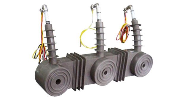
Product Show
 Zero-Sequence Protection Current Transformer Thomas Electric")
Working Principle
Primary conductors pass through a toroidal core composed of high‑permeability magnetic material. Variations in primary current cause proportional electromagnetic flux, which induces corresponding currents in secondary
windings. The zero‑sequence winding detects residual ground fault currents and provides integrated protective functionality in a compact unit.
System Application Position
- Medium‑Voltage Distribution: Outdoor 10–12 kV switchgear and distribution panels.
- Energy Metering: Current measurement and metering systems.
- Protection Circuits: Overcurrent and ground fault protection schemes.
- Automation & Grid Integration: Intelligent distribution monitoring and relay protection.
Structural Overview
Silicone rubber cast construction with fully-enclosed integrated design ensures superior insulation performance, moisture resistance, contamination resistance, and mechanical strength. The silicone rubber material provides exceptional resistance to high temperature, corrosion, UV radiation, and aging, ensuring long-term stable, reliable, and maintenance-free operation in outdoor environments. The compact, lightweight structure incorporates patented technology integrating A, B, C three-phase protection and zero-sequence ground protection in a single unit, optimizing space utilization in modern distribution systems while delivering high efficiency and reliability.
Model Designation
Code Explanation
 Zero-Sequence Protection Current Transformer Thomas Electric")
- LJ – Zero‑sequence current transformer series.
- ZW3 – Compatible with ZW2 vacuum circuit breaker.
- ZW43 – Compatible with ZW43 vacuum circuit breaker.
- 10(12) – System voltage: 10 kV or 12 kV.
Service Conditions
The LJ-ZW3/ZW43-10(12) series current transformers are designed for outdoor operation under normal service conditions in medium-voltage power distribution systems.
- Outdoor installation: suitable for pole‑mounted switchgear.
- Altitude: ≤ 2000 m (higher on request).
- Ambient temperature: −25 °C to +40 °C.
- Daily average temperature: ≤ 40 °C.
- Pollution level: Class II per IEC 60815.
- Environmental conditions: Free from corrosive gases or vapors; free from explosive or flammable media; no severe vibration, mechanical shock, or impact
Construction
Construction Design
- Structure: Integrated compact enclosed type for outdoor pole-mounted switchgear
- Insulation: Fully enclosed silicone rubber cast insulation with exceptional environmental resistance
- Core: Advanced high-permeability magnetic material core with precision multi-core winding configuration
- Multi-phase integration: Integrated three-phase (A, B, C) current measurement and zero-sequence protection in single compact unit
- System: Integrated primary and secondary insulation system with superior anti-tracking and anti-aging properties
The silicone rubber casting provides stable insulation properties and exceptional resistance to high temperature, corrosion, UV radiation, contamination, moisture, impact, and aging, ensuring maintenance-free long-term outdoor service under harsh environmental conditions.
Windings & Terminal Marking
- Primary terminals: P1 / P2 (per phase as applicable)
- Secondary terminals: S1 / S2 (per phase configuration, A/B/C phases)
- Zero-sequence terminals: As specified per configuration
Terminal markings follow standard CT polarity conventions. Under normal operating conditions, the reference current direction is defined from P1 to P2. Correct terminal identification shall be observed to ensure metering and protection performance. The integrated design simplifies wiring and reduces installation complexity in pole-mounted switchgear applications.
Technical Data
This section provides technical data for the LJ‑ZW3/ZW43‑10(12) series outdoor current transformers with zero‑sequence protection, designed for 10 kV / 12 kV systems. The compact design ensures high accuracy and stability for energy metering, protection, and fault detection.
Definitions: Rated primary current refers to the nominal current, while rated output (VA) applies per secondary core. Accuracy class 5P10 ensures protection‑grade accuracy with a limit factor of 10. Only one current ratio can be used during operation.
Typical configurations; final specification per project requirements and nameplate data.
| Model | Primary Current Range (A) |
Secondary (A) |
Accuracy | Output (VA) |
Insulation (kV) |
|---|---|---|---|---|---|
| LJ‑ZW3‑10(12) | 20–1200 | 5 (1) | 5P10 | 2.5–40 | 10(12)/42 |
| Multi‑ratio configurations available; consult factory. | |||||
| LJ‑ZW43‑10(12) | 20–1200 | 5 (1) | 5P10 | 2.5–40 | 10(12)/42 |
| Multi‑ratio configurations available; consult factory. | |||||
| Zero‑sequence protection core included in all configurations. | |||||
Standards & Normative References
| Standard | Description | Scope |
|---|---|---|
| GB 1208‑2006 | Current Transformers | Primary national standard for CT requirements |
| GB/T 20840.2 | Instrument Transformers – Part 2 | CT requirements aligned with IEC |
| IEC 61869‑1 | Instrument Transformers – Part 1 | General requirements |
| IEC 61869‑2 | Instrument Transformers – Part 2 | CT specific requirements |
| IEC 60815 | Insulator selection for pollution conditions | Pollution level guidance |
Factory Test Compliance
- Routine tests per applicable GB requirements (including polarity/marking, ratio verification, and accuracy verification per specified class and burden for all cores)
- Dielectric tests per insulation coordination requirements and applicable standard
- Visual and dimensional inspection including marking and workmanship conformity
- Type and special tests as required by the project specification
Installation & Dimensions
Outline
 Zero-Sequence Protection Current Transformer Thomas Electric")
- Outline dimensions and mounting details are provided in the dimensional drawings.
- The transformer shall be securely mounted to the pole-mounted switchgear structure using the designated fixing holes.
- Primary conductor connection is made via busbar through the window aperture for each phase.
- The integrated design simplifies installation and reduces on-site wiring complexity.
- Adequate clearance shall be maintained for insulation, heat dissipation, and maintenance access.
- Installation shall comply with manufacturer’s instructions and local electrical safety codes.
Safety Notes
- Secondary circuit must never be left open when the transformer is energized, as dangerous high voltage may appear across the secondary terminals.
- During inspection or maintenance, the secondary circuit shall be short-circuited before disconnecting any instruments.
- One point of the secondary circuit should be reliably grounded in accordance with applicable standards.
- All installation and maintenance work shall comply with local electrical safety regulations.
Ordering Information
When placing an order, the required configuration shall be specified according to the local grid requirements, applicable standards, and project technical specification. The following parameters shall be clearly stated for technical confirmation and production release:
- Model designation (LJ-ZW3 or LJ-ZW43)
- System voltage (10 kV or 12 kV)
- Rated primary current / transformation ratios (specify all required ratios if multi-ratio configuration)
- Rated secondary current (5 A or 1 A)
- Accuracy class (typically 5P10 for protection applications)
- Rated burden (VA) for each secondary core
- Number of phases (three-phase integrated configuration)
- Zero-sequence configuration requirements