Product Overview
Functional Definition
The LZW43-10 and LJ-ZW32-10(12) Outdoor Current Transformers are precision electromagnetic instruments specifically engineered for ZW32 and ZW43 vacuum circuit breakers, providing accurate current measurement and comprehensive fault protection capabilities. These transformers utilize advanced silicone rubber insulation technology, offering superior pollution resistance, moisture resistance, and arc tracking performance. The voltage withstand capability against humidity and contamination exceeds traditional outdoor epoxy resin products by 2.5 times. With robust structural impact resistance, excellent anti-creepage performance, and explosion-proof characteristics, these current transformers deliver significantly enhanced structural and electrical performance compared to previous generations. They are extensively deployed in pole-mounted switchgear applications, ensuring safe and reliable operation in challenging outdoor environments.
Key Ratings
| Item | Specification (per order / nameplate) |
|---|---|
| System voltage class | 10 kV / 12 kV class (outdoor pole-mounted distribution applications) |
| Rated frequency | 50 Hz (60 Hz available upon request) |
| Primary current range | 20 A to 1200 A (multi-tap configurations available) |
| Rated secondary current | 5 A (1 A available upon request) |
| Accuracy class | 10P10 (protection core) |
| Rated output | 5 VA to 40 VA (depending on primary current rating) |
| Burden power factor | cosφ = 0.8 (lagging) unless otherwise specified |
| Insulation level | 10(12)/42 kV (Um/Up) |
| Applicable standards | IEC 61869-1 / IEC 61869-2; GB/T 20840.1 / 20840.2; GB 1208-1997 |
| Compatible equipment | ZW43 and ZW32 series vacuum circuit breakers |
| Insulation material | Advanced silicone rubber (superior pollution and moisture resistance) |
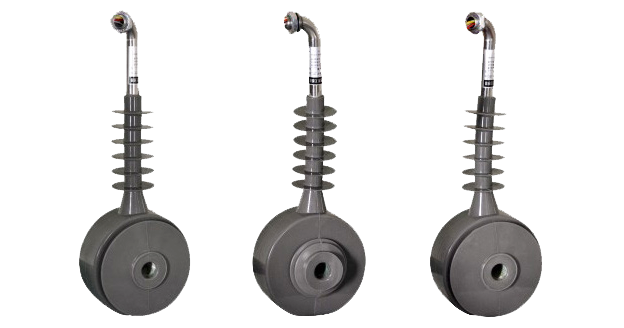
Product Shows
 Outdoor Current Transformers for ZW32/ZW43 Circuit Breakers Thomas Electric")
Working Principle
Operating on Faraday’s law of electromagnetic induction, the transformer features an oil-immersed toroidal magnetic core configuration with the primary conductor passing through the aperture and secondary windings precisely wound around the core. The magnetic flux generated by primary current induces proportional voltage in the secondary winding, delivering standardized output current through the connected burden. The advanced silicone rubber insulation system provides superior environmental protection while maintaining excellent dielectric properties for reliable long-term outdoor operation.
System Application Position
- Medium Voltage Distribution: 10-12kV pole-mounted switchgear and outdoor distribution systems
- Vacuum Circuit Breaker Integration: Dedicated compatibility with ZW32 and ZW43 series vacuum circuit breakers
- Protection Circuits: Overcurrent, earth fault, and distance protection schemes in distribution networks
- Distribution Automation: Remote monitoring and control systems for smart grid applications
- Outdoor Installations: Harsh environmental conditions including high pollution and moisture exposure
Structural Overview
Oil-immersed construction with advanced silicone rubber housing ensures exceptional insulation performance, superior pollution resistance, and outstanding moisture protection. The housing material delivers 2.5 times the voltage withstand capability of traditional epoxy resin products under contaminated and humid conditions. The pole-mounted configuration provides compact installation for outdoor applications while maintaining robust mechanical strength, explosion-proof characteristics, and excellent anti-creepage properties for extended service life in challenging environmental conditions.
Model Designation
 Outdoor Current Transformers for ZW32/ZW43 Circuit Breakers Thomas Electric")
Model Code Explanation
- L — Current transformer (CT)
- Z — Support (pillar) type
- W — Outdoor installation
- 43 / 32 — Compatible with ZW43 or ZW32 vacuum circuit breaker series
- 10 / 12 — Voltage class (kV)
Series Differences
LZW43-10(12) and LJ-ZW32-10(12) are designed for specific vacuum circuit breaker compatibility. LZW43 series are engineered for integration with ZW43 vacuum circuit breakers, while LJ-ZW32 series are configured for ZW32 vacuum circuit breaker applications. When specified with identical primary current ratings, accuracy classes, and rated outputs, both series provide equivalent electrical performance. Selection between series is primarily determined by the specific vacuum circuit breaker model deployed in the distribution system and mechanical mounting requirements.
Service Conditions
The LZW43-10 / LJ-ZW32-10(12) series current transformers are designed for outdoor operation under normal service conditions in medium-voltage pole-mounted distribution systems.
- Installation environment: Outdoor pole-mounted installation
- Altitude: Not exceeding 1000 m above sea level (higher altitude applications shall be specified for engineering confirmation)
- Ambient temperature: −5 °C to +40 °C
- Relative humidity: Daily average ≤ 95%, monthly average ≤ 90% (at +20 °C reference)
- Pollution grade: Grade II pollution environment (higher grades may require special consideration)
- Environmental conditions: Suitable for outdoor installations without harmful gases or severe contamination; designed to withstand environmental stress including wind, rain, and temperature cycling
Construction
Construction Design
- Structure: Support (post) type for outdoor pole-mounted installation
- Insulation: Oil-immersed design with advanced silicone rubber housing
- Core: Ring-type magnetic core design
- Housing material: Silicone rubber with superior anti-pollution and moisture resistance properties
- Environmental protection: Voltage withstand capability 2.5 times higher than traditional epoxy resin products under contaminated conditions
- Mechanical properties: Enhanced impact resistance with excellent anti-creepage performance
- Safety features: Explosion-proof design for enhanced operational safety
The advanced silicone rubber insulation system provides exceptional resistance to moisture, contamination, tracking, and environmental aging, ensuring reliable long-term performance in demanding outdoor service conditions. The oil-immersed core configuration enhances thermal management and magnetic performance stability.
Windings & Terminal Marking
- Primary terminals: P1 / P2
- Secondary terminals: S1 / S2
Terminal markings follow standard CT polarity conventions per IEC 61869 and GB standards. Under normal operating conditions, the reference current direction is defined from P1 to P2. Correct terminal identification and polarity observation shall be strictly maintained to ensure proper protection relay operation and coordination.
Technical Data
This section provides selection-oriented technical data for the LZW43-10(12) and LJ-ZW32-10(12) series outdoor, oil-immersed current transformers with silicone rubber housing, used in 10 kV and 12 kV class AC systems (50 Hz). Data shown below is intended for preliminary selection of primary current ratings, accuracy class, and rated output combinations tailored for protection applications with ZW32 and ZW43 vacuum circuit breakers.
Definitions: Rated primary current indicates the nominal operating current level of the transformer. Rated output (VA) is specified for the protection core and increases with higher primary current ratings to accommodate relay burden requirements. Insulation level is expressed as Um/Up where Um is the maximum system voltage and Up is the lightning impulse withstand voltage.
Notation: The 10P10 accuracy class designation indicates a protection core with 10% composite error at the accuracy limit factor (ALF) of 10 times rated primary current, suitable for standard overcurrent and earth fault protection applications.
Data Reference
| Model | Rated Primary Current (A) |
Rated Secondary Current (A) |
Accuracy Class & Rated Output (VA) |
Insulation Level (kV) |
|---|---|---|---|---|
| LZW32-10(12) LZW43-10(12) |
20 / 30 / 50 | 5 (1) | 10P10: 5 / 10 / 10 VA | 10(12)/42 |
| 50 / 100 / 150 | 5 (1) | 10P10: 10 / 15 / 15 VA | 10(12)/42 | |
| 100 / 200 / 300 | 5 (1) | 10P10: 10 / 15 / 15 VA | 10(12)/42 | |
| LZW32-10(12) LZW43-10(12) |
200 / 400 / 600 | 5 (1) | 10P10: 10 / 15 / 20 VA | 10(12)/42 |
| 600 / 1000 / 1200 | 5 (1) | 10P10: 20 / 30 / 40 VA | 10(12)/42 |
Standards & Normative References
| Standard | Title | Application |
|---|---|---|
| IEC 61869-1 | Instrument Transformers – Part 1: General Requirements | General requirements |
| IEC 61869-2 | Instrument Transformers – Part 2: Additional Requirements for Current Transformers | CT-specific requirements |
| GB/T 20840.1 | Instrument Transformers – Part 1: General Requirements | National standard (aligned with IEC 61869 framework) |
| GB/T 20840.2 | Instrument Transformers – Part 2: Current Transformers | National CT requirements (aligned with IEC 61869-2) |
| GB 1208-1997 | Current Transformers | National CT standard where specified by the project |
| IEEE C57.13 | Standard Requirements for Instrument Transformers | Optional (North America project reference) |
| IEC 60068-2-11 | Environmental Testing – Salt Mist | Optional (coastal installation validation) |
Factory Test Compliance
- Routine tests per applicable IEC/GB requirements (including polarity verification, ratio testing, and accuracy verification per specified class and burden)
- Dielectric tests per insulation coordination requirements and applicable standards (power frequency withstand and lightning impulse tests)
- Silicone rubber housing tests including tracking resistance, hydrophobicity, and mechanical strength verification
- Visual and dimensional inspection including marking verification and workmanship conformity assessment
- Type and special tests as required by the project specification (pollution performance, temperature cycling, seismic qualification)
Installation & Dimensions
- Outline dimensions and mounting details are provided in the dimensional drawings below for each series.
- The transformer shall be securely mounted to the pole-mounted switchgear structure using the designated fixing holes and hardware.
- Primary conductor connection is integrated with the vacuum circuit breaker mechanism per the specific breaker series (ZW43 or ZW32).
- Adequate clearance shall be maintained for insulation coordination, heat dissipation, and maintenance access per applicable standards.
- Terminal compartments shall be properly sealed against moisture ingress and contamination after wiring completion.
Outlines
 Outdoor Current Transformers for ZW32/ZW43 Circuit Breakers Thomas Electric")
LZW43-10(12) Installation Dimensions
 Outdoor Current Transformers for ZW32/ZW43 Circuit Breakers Thomas Electric")
LZW32-10(12) Installation Dimensions
Ordering Information
When placing an order, the required configuration shall be specified according to the vacuum circuit breaker model, local grid requirements, applicable standards, and project technical specification. The following parameters shall be clearly stated for technical confirmation and production release:
- Vacuum circuit breaker series: ZW43 or ZW32 (determines CT series selection)
- Voltage class: 10 kV or 12 kV system
- Rated primary current (select from available ratings: 20A to 1200A)
- Rated secondary current (standard 5 A or optional 1 A)
- Accuracy class: 10P10 (standard for protection applications)
- Rated burden (VA) corresponding to selected primary current rating
- Environmental conditions: Standard outdoor or enhanced pollution/coastal environment specifications
If local utility requirements, project specifications, or special installation conditions apply (e.g., enhanced insulation coordination, specific terminal arrangements, mounting modifications, documentation language requirements, or special certifications), specify them at the ordering stage. Special configurations shall be confirmed by technical agreement and final data sheet prior to production release.