Product Overview
Functional Definition
The LJ-ZW32-10(12) Zero-Sequence Protection Current Transformer are precision electromagnetic instruments designed for accurate current measurement, residual current monitoring, and relay protection applications in medium-voltage AC power systems (10 kV / 12 kV class). These transformers are specifically engineered for integration with ZW32-series vacuum circuit breakers, providing galvanically isolated secondary current signals proportional to primary current and zero-sequence fault detection capability for ground fault protection, line isolation, and alarm triggering.
Key Ratings
| Item | Specification (per order / nameplate) |
|---|---|
| System voltage class | 10 kV / 12 kV class (outdoor pole-mounted switchgear applications) |
| Rated frequency | 50 Hz (60 Hz available upon request) |
| Rated secondary current | 5 A (1 A available upon request) |
| Accuracy class | 5P10 (protection core) |
| Rated burden | 2.5 VA ~ 25 VA (per configuration) |
| Zero-sequence configuration | 20 A / 1 A (0.1 Ω); 50 A / 1 A (0.2 Ω) |
| Insulation level | 10(12) / 42 kV |
| Applicable standards | GB 1208-2006; GB/T 20840.2; IEC 61869-2 (reference) |
| Application environment | Outdoor installation; pollution level II |
Working Principle
Operating on Faraday’s law of electromagnetic induction, the transformer features a toroidal magnetic core with primary conductor passing through the aperture and secondary windings wound around the core. The magnetic flux generated by primary current induces proportional voltage in the secondary winding, delivering standardized output current through connected burden. Zero-sequence detection is achieved through dedicated winding configuration that senses residual current from ground faults or leakage currents.
System Application Position
- Medium Voltage Distribution: 10-12 kV outdoor pole-mounted switchgear and distribution panels with ZW32 vacuum circuit breakers
- Protection Circuits: Zero-sequence ground fault protection, overcurrent protection schemes
- Energy Metering: Current measurement and monitoring systems
- SCADA Integration: Supervisory control and data acquisition systems for fault detection and isolation
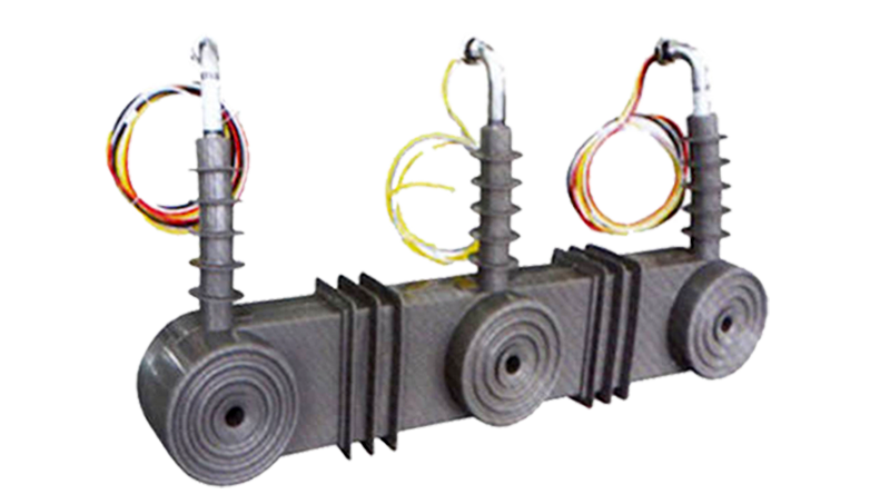
Structural Overview
Silicone rubber cast construction with fully-enclosed design ensures superior insulation performance, moisture resistance, contamination resistance, and mechanical strength. The wet-state dielectric performance is 1.5 to 2.5 times that of conventional epoxy resin products. The compact mounting configuration provides reliable installation in outdoor pole-mounted switchgear environments while maintaining excellent electrical clearance, impact resistance, and anti-tracking properties suitable for harsh outdoor conditions.
Model Designation
 Zero-Sequence Protection Current Transformer (outdoor) Thomas Electric")
Model Code Explanation
- LJ — Zero-sequence current transformer
- ZW32 — Compatible with ZW32 vacuum circuit breaker series
- 10(12) — Voltage class: 10 kV or 12 kV
Service Conditions
The LJ-ZW32-10(12) series current transformers are designed for outdoor operation under normal service conditions in medium-voltage power systems.
- Installation environment: Outdoor installation; suitable for pole-mounted switchgear
- Altitude: Not exceeding 2000 m above sea level (higher altitude shall be specified for engineering confirmation)
- Ambient temperature: −25 °C to +40 °C
- Daily average temperature: ≤ 40 °C
- Relative humidity: ≤ 95% maximum
- Pollution level: Class II per IEC 60815
- Environmental conditions: Free from corrosive gases or vapors; free from explosive or flammable media; no severe vibration, mechanical shock, or impact
Construction
Construction Design
- Structure: Compact enclosed type for outdoor pole-mounted switchgear
- Insulation: Fully enclosed silicone rubber cast insulation with superior wet-state performance
- Core: High-quality ring-type magnetic core with precision winding configuration
- Zero-sequence protection: Integrated zero-sequence winding for ground fault detection
- System: Integrated primary and secondary insulation system with enhanced tracking resistance
The silicone rubber casting provides stable insulation properties and exceptional resistance to moisture, contamination, UV radiation, impact, and aging for long-term outdoor service in harsh environments.
Windings & Terminal Marking
- Primary terminals: P1 / P2
- Secondary terminals (Phase cores): S1 / S2 (per phase configuration)
- Zero-sequence terminals: As specified per configuration
Terminal markings follow standard CT polarity conventions. Under normal operating conditions, the reference current direction is defined from P1 to P2. Correct terminal identification shall be observed to ensure metering and protection performance.
Technical Data
This section provides selection-oriented technical data for the LJ-ZW32-10(12) series outdoor, silicone rubber cast zero-sequence protection current transformer used in 10 kV / 12 kV class AC systems (50 Hz). Data shown below is intended for preliminary selection of current ratio, accuracy class, rated burden, and zero-sequence configuration.
Definitions: Rated primary current indicates the nominal operating current. Rated output (VA) is specified per secondary core. Zero-sequence configuration provides residual current detection for ground fault protection. Accuracy class 5P10 indicates protection-grade accuracy with accuracy limit factor of 10.
Data Reference
| Type | Rated Primary Current (A) |
Rated Secondary Current (A) |
Accurate & Rated Output (VA) | Rated Insulation Level (kV) |
|||
|---|---|---|---|---|---|---|---|
| 5P10 | |||||||
| LJ-LZW32-10(12) | 100, 150, 200 | 5(1) | 2.5 | 3.74 | 5 | 10(12)/42 | |
| 100, 200, 300 | 2.5 | 5 | 7.5 | ||||
| 200, 300, 400 | 5 | 7.5 | 10 | ||||
| 200, 400, 600 | 5 | 10 | 15 | ||||
| 600, 800, 1000 | 15 | 20 | 25 | ||||
| 800, 1000, 1200 | 15 | 20 | 25 | ||||
| Zero Sequence | 20 | 1 | 0.1Ω | ||||
| 50 | 0.2Ω | ||||||
Customization Note: Custom configurations including special current ratios, high-accuracy combinations, and enhanced insulation levels are available upon request. During operation, only one current ratio can be used at a time; multiple ratios cannot be used simultaneously. This product utilizes patented integrated design combining three-phase protection (A, B, C) and zero-sequence ground fault protection in a compact, lightweight structure suitable for intelligent power distribution systems.
Standards & Normative References
| Standard | Title | Application |
|---|---|---|
| GB 1208-2006 | Current Transformers | Primary national standard for CT requirements |
| GB/T 20840.2 | Instrument Transformers – Part 2: Current Transformers | National CT requirements (aligned with IEC 61869-2) |
| IEC 61869-1 | Instrument Transformers – Part 1: General Requirements | International general requirements (reference) |
| IEC 61869-2 | Instrument Transformers – Part 2: Additional Requirements for Current Transformers | International CT-specific requirements (reference) |
| IEC 60815 | Selection and Dimensioning of High-Voltage Insulators for Polluted Conditions | Pollution level classification |
Factory Test Compliance
- Routine tests per applicable GB requirements (including polarity/marking, ratio verification, and accuracy verification per specified class and burden)
- Dielectric tests per insulation coordination requirements and applicable standard
- Visual and dimensional inspection including marking and workmanship conformity
- Type and special tests as required by the project specification
Installation & Dimensions
Outline
 Zero-Sequence Protection Current Transformer (outdoor) Thomas Electric")
- Outline dimensions and mounting details are provided in the dimensional drawings.
- The transformer shall be securely mounted to the pole-mounted switchgear structure using the designated fixing holes.
- Primary conductor connection is made via busbar through the window aperture.
- Adequate clearance shall be maintained for insulation, heat dissipation, and maintenance access.
- Installation shall comply with manufacturer’s instructions and local electrical safety codes.
Safety Notes
- Secondary circuit must never be left open when the transformer is energized, as dangerous high voltage may appear across the secondary terminals.
- During inspection or maintenance, the secondary circuit shall be short-circuited before disconnecting any instruments.
- One point of the secondary circuit should be reliably grounded in accordance with applicable standards.
- All installation and maintenance work shall comply with local electrical safety regulations.
Ordering Information
When placing an order, the required configuration shall be specified according to the local grid requirements, applicable standards, and project technical specification. The following parameters shall be clearly stated for technical confirmation and production release:
- Rated primary current / transformation ratio
- Rated secondary current (5 A or 1 A)
- Accuracy class (typically 5P10 for protection applications)
- Rated burden (VA) for secondary core
- Zero-sequence configuration (20 A or 50 A)
- System voltage (10 kV or 12 kV)
How to select:
1. Determine rated primary current based on feeder/load rating and expected operating range.
2. Select protection accuracy requirements (typically 5P10 for zero-sequence protection).
3. Confirm rated burden (VA) based on connected protection relays and wiring losses.
4. Specify zero-sequence configuration (20 A or 50 A) based on ground fault detection requirements.
5. Specify system voltage class (10 kV or 12 kV).
If local utility or project requirements apply (e.g., enhanced insulation level, special terminal arrangement, mounting constraints, documentation language, or required certificates), specify them at the ordering stage. Special configurations shall be confirmed by technical agreement and final data sheet prior to production.