Product Overview
Functional Definition
The LJK-φ100~φ240 series zero-sequence current transformers are precision electromagnetic instruments designed for ground fault detection, residual current monitoring, and earth leakage protection in low and medium-voltage AC power distribution systems. These transformers utilize electromagnetic induction principles to detect unbalanced current (zero-sequence component) in three-phase systems, providing isolated secondary current signals for relay protection and fault location applications.

Key Ratings
| Item | Specification |
|---|---|
| Voltage range | 0.4 kV ~ 66 kV |
| Frequency range | 0 ~ 500 Hz (supports 3rd harmonic 150 Hz, 5th harmonic 250 Hz) |
| Aperture diameter | φ100 mm ~ φ240 mm |
| Accuracy classes | 0.2, 0.5, 1.0, 3.0 (as specified) |
| Rated burden | 5 VA, 10 VA, 15 VA (as specified) |
| Secondary terminals | K1, K2 |
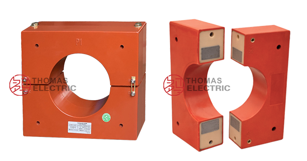
| Installation type | Split-core (openable) structure for retrofit installation |
| Enclosure material | ABS engineering plastic with epoxy resin sealed core |
| Protection rating | IP54 (indoor application) |
| Application | Ground fault protection, residual current detection, earth leakage monitoring |
Working Principle
Operating on Faraday’s law of electromagnetic induction, the zero-sequence current transformer features a ring-type magnetic core that encircles all three-phase conductors and the neutral conductor (if present). Under balanced three-phase conditions, the vector sum of currents is zero, producing no magnetic flux in the core. When ground fault or leakage occurs, the unbalanced current (zero-sequence component) generates magnetic flux in the core, inducing proportional voltage in the secondary winding. This secondary current signal activates protective relays or monitoring devices.
System Application Position
- Low-Voltage Distribution: 0.4 kV distribution panels and motor control centers
- Medium-Voltage Systems: 6-35 kV cable circuits and overhead lines
- Ground Fault Protection: Selective earth fault protection schemes
- Residual Current Monitoring: Continuous leakage current surveillance
- Cable Monitoring: Cable insulation condition assessment
Structural Overview
ABS engineering plastic enclosure with epoxy resin fully-sealed core construction ensures superior insulation performance, moisture resistance, and corrosion protection. The split-core (openable) design enables installation on existing cable circuits without disconnection, providing exceptional convenience for retrofit applications and maintenance. Anti-rust treatment and thermal management enhance long-term stability in harsh indoor environments.
Model Designation

Model Code Explanation
- L — Current transformer (CT)
- J — Ground (earth) protection application
- K — Split-core (openable/split-type) structure
- φ100~φ240 — Inner aperture diameter (mm)
Service Conditions
The LJK-φ100~φ240 series zero-sequence current transformers are designed for indoor operation under normal service conditions in power distribution systems.
Installation Environments
- Installation environment: Indoor installation only
- Altitude: Not exceeding 2000 m above sea level (higher altitude requires specification at ordering)
- Ambient temperature: −25 °C to +40 °C
- Relative humidity: ≤ 95% (no condensation)
- Environmental conditions: Free from conductive dust, metallic particles, corrosive gases, or mold; no severe vibration or mechanical shock
Construction
Construction Design
- Structure: Ring-type with split-core (openable) configuration
- Insulation: Epoxy resin fully-sealed core with ABS engineering plastic enclosure
- Core: High-permeability magnetic core for sensitive zero-sequence detection
- Terminals: Secondary terminals K1, K2 with connecting link
- Treatment: Anti-rust coating for long-term environmental stability
The epoxy resin sealing provides stable insulation properties and resistance to moisture, contamination, and aging. The split-core design allows installation without primary conductor disconnection.
Windings & Terminal Marking
- Primary conductor: All three-phase conductors (and neutral if present) pass through the aperture
- Secondary terminals: K1 / K2
The reference current direction is defined by the primary conductor passing through the L1 face of the transformer. Terminal markings follow standard CT polarity conventions. Correct terminal identification shall be observed to ensure protection performance.
Technical Data
This section provides technical specifications for the LJK-φ100~φ240 series zero-sequence current transformers for indoor distribution systems. Data includes dimensional specifications and electrical parameters for preliminary selection.
Data Reference
Accuracy class indicates the proportional difference between actual and measured current values under specified conditions.
Standards & Normative References
| Standard | Title | Application |
|---|---|---|
| IEC 61869-1 | Instrument Transformers – Part 1: General Requirements | General requirements |
| IEC 61869-2 | Instrument Transformers – Part 2: Additional Requirements for Current Transformers | CT-specific requirements |
| GB/T 20840.1 | Instrument Transformers – Part 1: General Requirements | National standard (IEC-aligned) |
| GB/T 20840.2 | Instrument Transformers – Part 2: Current Transformers | National CT requirements |
| GB 1208-2006 | Current Transformers | National CT standard |
| DL/T 866-2004 | Technical Specification for Current Transformers and Voltage Transformers | Power industry technical specification |
Factory Test Compliance
- Routine tests per IEC 61869 and GB/T 20840 requirements (including polarity verification, ratio verification, and accuracy verification per specified class and burden)
- Insulation resistance test per insulation coordination requirements
- Dielectric withstand test per applicable standard
- Visual and dimensional inspection including marking verification and workmanship conformity
- Environmental tests as required by project specification (temperature, humidity, vibration)
Installation & Dimensions

Dimensional Specifications
| Model | A | B | C | E | F | a | b | D(φ) | d(φ) |
|---|---|---|---|---|---|---|---|---|---|
| LJK-100 | 214 | 190 | 141 | 50 | 188 | 152 | 184 | 102 | 9 |
| LJK-120 | 232 | 208 | 160 | 50 | 206 | 170 | 202 | 120 | 9 |
| LJK-140 | 275 | 255 | 178 | 71 | 245 | 200 | 255 | 145 | 9 |
| LJK-160 | 293 | 267 | 195 | 71 | 262 | 220 | 271 | 165 | 9 |
| LJK-180 | 317 | 290 | 255 | 71 | 302 | 260 | 297 | 187 | 9 |
| LJK-200 | 370 | 348 | 285 | 85 | 330 | 310 | 340 | 206 | 9 |
| LJK-240 | 410 | 383 | 315 | 79 | 383 | 336 | 390 | 246 | 10.5 |
Note: All dimensions in millimeters (mm). For special installation configurations, contact technical support for customized dimensional drawings.
Installation Instructions
Closed-Core Type Installation (if applicable)
Closed-core transformers must be installed before cable laying and positioning shall be verified before energization.
Split-Core Type Installation
Split-core transformers can be installed on energized or de-energized circuits. Installation procedure:
- Remove the connecting link between K1 and K2 terminals
- Unscrew the fastening screws and separate the transformer into upper and lower halves
- Position the transformer around the cable bundle or busbar
- Clean the mating surfaces and apply anti-rust compound
- Align the halves precisely and tighten the fastening screws securely
- Reinstall the K1-K2 connecting link
Safety Notes
- Secondary circuit must never be left open when the primary conductor is energized
- During inspection or maintenance, short-circuit the secondary terminals before disconnecting protection devices
- One point of the secondary circuit should be reliably grounded in accordance with protection coordination requirements
- All installation and maintenance work shall comply with local electrical safety regulations
- Adequate clearance shall be maintained for insulation, heat dissipation, and maintenance access
Ordering Information
When placing an order, specify the required configuration according to system requirements and protection coordination. The following parameters shall be clearly stated for technical confirmation:
Selection Guidance
- Voltage level: System nominal voltage (e.g., 0.4 kV ~ 66 kV)
- Aperture diameter: Based on cable bundle size or busbar dimensions (φ100 ~ φ240 mm)
- Accuracy class: Per protection relay requirements (e.g., 0.5, 1.0, 3.0)
- Rated burden: Based on connected relay burden and wiring losses (e.g., 5 VA, 10 VA, 15 VA)
- Installation type: Split-core or closed-core (specify if special mounting required)
- Operating environment: Temperature range, humidity, altitude, special environmental conditions
- Custom requirements: Special aperture sizes, accuracy classes, environmental adaptations, or installation configurations
Selection Process:
- Determine aperture diameter based on cable bundle or busbar dimensions with adequate clearance
- Select accuracy class based on ground fault protection sensitivity requirements
- Confirm rated burden based on connected protective relay specifications and wiring impedance
- Verify environmental compatibility (temperature range, humidity, installation location)
- Specify special requirements (if any) for factory confirmation