Product Overview
Functional Definition
The LJW1-35 and LJWD1-35 series, 35KV Oil-Immersed Current Transformers are precision electromagnetic instruments designed for accurate current measurement, energy metering, and relay protection applications in 35kV AC power systems. These transformers utilize electromagnetic induction principles with oil-paper insulation to provide galvanically isolated secondary current signals proportional to primary current in both indoor and outdoor installations.
Key Ratings Snapshot
| Item | Specification (per order / nameplate) |
|---|---|
| System voltage class | 35 kV class (indoor and outdoor applications) |
| Rated frequency | 50 Hz (60 Hz available upon request) |
| Rated secondary current | 5 A |
| Accuracy classes | Metering: 0.2, 0.5, 1; Protection: 3(D) as specified |
| Continuous thermal rating | 120% of rated primary current |
| Insulation level | 40.5/95/1200 kV (Um/Ud/Ui) |
| Creepage distance | Standard: ≥735 mm; W2 type: ≥1100 mm |
| Applicable standards | IEC 61869-1 / IEC 61869-2; GB/T 20840.1 / 20840.2; GB 1208-1997 |
| Structural variants | LJW1-35 (single-winding) / LJWD1-35 (dual-winding) |
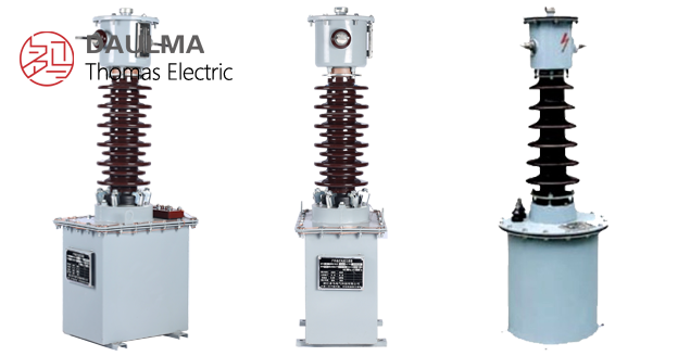
Product Show

Working Principle
Operating on Faraday’s law of electromagnetic induction, the transformer features a toroidal magnetic core with primary conductor passing through the aperture and secondary windings wound around the core. The oil-paper insulation system provides superior dielectric strength and thermal stability. The magnetic flux generated by primary current induces proportional voltage in the secondary winding, delivering standardized 5A output current through connected burden.
System Application Position
- Medium Voltage Distribution: 35kV switchgear and distribution substations
- Energy Metering: Revenue-grade electricity measurement systems
- Protection Circuits: Overcurrent, differential, and distance protection schemes
- SCADA Integration: Supervisory control and data acquisition systems
Structural Overview
Steel tank oil-immersed construction with oil-paper insulation ensures superior dielectric strength, excellent heat dissipation, and long-term operational reliability. The outdoor-rated design provides weather-resistant enclosure suitable for both indoor switchgear and outdoor substations. The product employs vacuum oil filtration and vacuum oil impregnation processes to enhance insulation performance and thermal efficiency.
Model Designation

Model Code Explanation
- L — Current transformer (CT)
- J — Oil-immersed (oil-paper insulation)
- W — Outdoor application (weather-resistant)
- D — Dual-winding configuration (LJWD1 only; omitted for single-winding LJW1)
- 1 — Design code (platform/iteration)
- 35 — Voltage class (kV)
Variant Differences
LJW1-35 provides single secondary winding for metering or protection. LJWD1-35 provides dual independent secondary windings, allowing simultaneous metering and protection cores with separate accuracy classes and burdens. Both variants share identical oil-immersed steel tank construction and electrical insulation characteristics.
Service Conditions
The LJW1-35 / LJWD1-35 series current transformers are designed for indoor and outdoor operation under normal service conditions in 35kV power systems.
- Installation environment: Indoor and outdoor installation
- Altitude: Not exceeding 4000 m above sea level (higher altitude requires engineering confirmation)
- Ambient temperature: −25 °C to +40 °C
- Pollution level: Class II pollution area
- Environmental conditions: Free from corrosive gases or vapors; free from explosive or flammable media; no severe vibration, mechanical shock, or impact
Construction
Construction Design
- Structure: Single-phase oil-immersed self-cooled type
- Insulation: Oil-paper insulation system with steel tank enclosure
- Core: Ring-type magnetic core design
- Processing: Vacuum oil filtration and vacuum oil impregnation
- Tank design: Breathing device with waterproof/snow protection cap; diaphragm isolation to minimize oil oxidation
The oil-paper insulation provides stable dielectric properties and superior thermal performance compared to dry-type designs. The steel tank construction with breathing apparatus allows thermal expansion while protecting internal components from moisture ingress and environmental contamination.
Thermal & Dynamic
The oil-immersed construction delivers enhanced short-circuit withstand capability: thermal stability rating reaches 75 times conventional designs, while dynamic stability achieves 187.5 times conventional performance. This superior fault tolerance supports reliable operation under system fault conditions.
Windings & Terminal Marking

- Primary terminals: P1 / P2
- Secondary terminals (LJW1-35): S1 / S2
- Secondary terminals (LJWD1-35, Winding 1): 1S1 / 1S2
- Secondary terminals (LJWD1-35, Winding 2): 2S1 / 2S2
Terminal markings follow standard CT polarity conventions. Under normal operating conditions, the reference current direction is defined from P1 to P2. Correct terminal identification shall be observed to ensure metering and protection performance.
Technical Data
This section provides selection-oriented technical data for the LJW1-35 / LJWD1-35 series oil-immersed current transformers used in 35 kV class AC systems (50 Hz). Data shown below is intended for preliminary selection of current ratio, accuracy class combinations, rated burdens, and output capacity.
Definitions: Accuracy class combination indicates available metering/protection cores in one CT (multi-core configuration may apply). Rated output (VA) is specified per secondary core. Burden power factor cosφ = 0.8 (lagging) unless otherwise specified.
Technical Parameters
| Model | Voltage Class (kV) | Current Ratio (A) | Rated Output 0.2 Class (VA) |
|---|---|---|---|
| LJW1-35 | 35 | 5~600/5 | 30~50 |
| LJWD1-35 | 35 | 5~600/5 | 30~50 |
Standards & Normative References
| Standard | Title | Application |
|---|---|---|
| IEC 61869-1 | Instrument Transformers – Part 1: General Requirements | General requirements |
| IEC 61869-2 | Instrument Transformers – Part 2: Additional Requirements for Current Transformers | CT-specific requirements |
| GB/T 20840.1 | Instrument Transformers – Part 1: General Requirements | National standard (IEC aligned) |
| GB/T 20840.2 | Instrument Transformers – Part 2: Current Transformers | National CT requirements |
| GB 1208-1997 | Current Transformers | National CT standard |
Factory Test Compliance
- Routine tests per applicable IEC/GB requirements (including polarity/marking, ratio verification, and accuracy verification per specified class and burden)
- Dielectric tests per insulation coordination requirements and applicable standard
- Oil quality tests including dielectric strength and moisture content verification
- Visual and dimensional inspection including marking and workmanship conformity
- Type and special tests as required by the project specification
Installation & Dimensions
- Outline dimensions and mounting details are provided in the dimensional drawings.
- The transformer shall be securely mounted using the designated fixing holes and mounting base.
- Primary conductor connection shall be made via bolted terminals with appropriate torque specification.
- Adequate clearance shall be maintained for insulation, heat dissipation, and maintenance access.
- Oil level indicator shall be checked regularly per maintenance schedule.
Safety Notices
- During inspection or maintenance, the secondary circuit shall be short-circuited before disconnecting any instruments.
- One point of the secondary circuit should be reliably grounded in accordance with applicable standards.
- All installation and maintenance work shall comply with local electrical safety regulations.
- Oil quality shall be monitored and maintained per manufacturer specifications.
Ordering Information
When placing an order, the required configuration shall be specified according to the local grid requirements, applicable standards, and project technical specification. The following parameters shall be clearly stated for technical confirmation and production release:
- Rated primary current / transformation ratio
- Rated secondary current (5 A)
- Application and accuracy requirements (metering and/or protection accuracy class combination)
- Rated burden (VA) for each secondary core/winding
- Insulation level and environmental specifications (altitude, pollution level, creepage distance requirements)
Selection Guidance
1. Determine rated primary current (Ip) based on feeder/load rating and expected operating range.
2. Select metering and/or protection accuracy requirements (e.g., 0.2 / 0.5 for metering; 3(D) for protection).
3. Confirm rated burden (VA) for each secondary circuit based on connected meters/relays and wiring losses.
4. Verify insulation level matches system voltage and environmental conditions.
5. Specify any special requirements such as extended creepage distance (W2 type), high-altitude operation, or custom dimensions.
If local utility or project requirements apply (e.g., specific insulation level, terminal arrangement, mounting constraints, documentation language, or required certificates), specify them at the ordering stage. Special configurations shall be confirmed by technical agreement and final data sheet prior to production.