Product Overview
Functional Definition
The LXK-120 split-core zero-sequence current transformer (core-balance CT) is a protective current transformer designed for earth-fault (zero-sequence) detection in low and medium-voltage AC power systems up to 10 kV. Based on electromagnetic induction, it detects residual (zero-sequence) current as the vector sum of phase currents passing through the aperture, providing a reliable input signal for relay protection or alarm indication during ground fault conditions.
Key Ratings
| Item | Specification (per order / nameplate) |
|---|---|
| System voltage class | ≤10 kV (indoor distribution and protection applications) |
| Rated frequency | 50 Hz / 60 Hz |
| Rated secondary current | 1 A or 5 A |
| Accuracy classes | 10P5 to 10P20 (protection cores as specified) |
| Rated burden | 1–15 VA (depending on configuration) |
| Insulation level | 0.72/3 kV (rated insulation voltage / power-frequency withstand voltage) |
| Cable aperture diameter | 120 mm (aperture diameter; verify cable OD and installation clearance) |
| Ambient temperature | −25 °C to +40 °C |
| Structure type | Split-core (clamshell) design with stainless steel fastening band |
| Applicable standards | GB/T 20840.1-2010; GB/T 20840.2-2014 (aligned with IEC 61869 framework) |
| Installation method | Cable-type (core-balance), retrofit installation without cable disconnection |
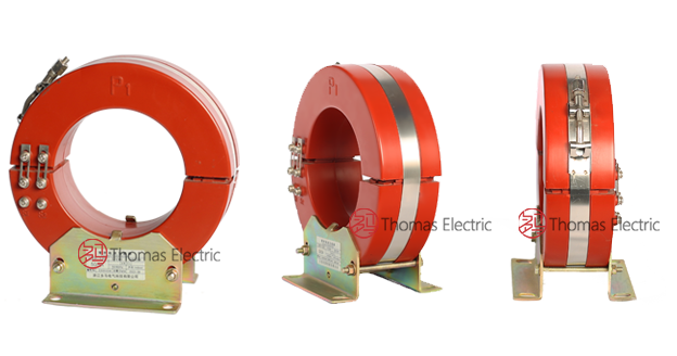
Product Shows
 Thomas Electric")
 Thomas Electric")
Working Principle
Under normal balanced operating conditions, the vector sum of three-phase currents passing through the aperture is approximately zero, producing negligible resultant magnetic flux in the transformer core. During an earth fault, residual (zero-sequence) current becomes non-zero and generates magnetic flux in the toroidal core. This flux induces a proportional secondary signal, which drives current through connected protection relays or monitoring devices to initiate trip action or alarm indication according to system protection settings.
System Application Position
- Zero-Sequence Protection: Earth-fault detection and protection in ≤10 kV distribution systems
- Generator Protection: Three-phase AC generator stator ground fault protection
- Motor Protection: MV motor ground fault and single-phase-to-ground protection (6–10 kV class)
- Distribution Systems: Indoor switchgear, busbar chambers, and cable distribution networks
- Relay Integration: Electromagnetic, electronic, and microprocessor-based protection relays
Structural Overview
Indoor epoxy resin cast construction with a split-core (clamshell) mechanical design enables installation around existing cables without system disconnection. The assembly consists of two semi-circular cast resin sections secured by a stainless steel fastening band, providing stable insulation performance, moisture resistance, and mechanical integrity. The cable-type configuration eliminates primary terminals and simplifies field installation in confined switchgear environments.
Model Designation
 Thomas Electric")
Model Code Explanation
- L — Current transformer (CT)
- X — Zero-sequence (residual current detection)
- K — Split-core (clamshell opening) structure
- 120 — Nominal aperture diameter (mm)
Series Variants
The LXK series is available in multiple aperture sizes to accommodate different cable diameters and installation requirements: LXK-φ80, LXK-φ100, LXK-φ120, LXK-φ150, LXK-φ180, LXK-φ200, LXK-φ240, and LXK-φ260. Each variant shares the same operating principle and construction methodology; aperture size is the primary mechanical difference.
Service Conditions
The LXK-120 zero-sequence current transformer is designed for indoor operation under normal service conditions in low and medium-voltage power systems.
- Installation environment: Indoor installation only
- Altitude: ≤ 1000 m (higher altitude requires engineering confirmation)
- Ambient temperature: −25 °C to +40 °C
- Relative humidity: Daily average ≤ 95%, monthly average ≤ 90%
- Environmental conditions: Free from corrosive gases/vapors, explosive or flammable media; no severe vibration, mechanical shock, or impact
- Outdoor application: Not suitable for outdoor service; if required, use an appropriate enclosure and consult factory
Construction
Construction Design
- Structure: Split-core (clamshell) cable-type configuration for retrofit installation
- Insulation: Fully enclosed epoxy resin cast insulation with protective outer shell
- Core: Ring-type (toroidal) magnetic core optimized for residual current detection
- Fastening system: Stainless steel band clamp for mechanical integrity and corrosion resistance
- Corrosion protection: Anti-corrosion treatment for metallic components (as applicable)
The epoxy resin casting provides stable insulation properties and resistance to moisture, contamination, and aging for long-term indoor service. The split-core design allows installation around existing cables without disconnecting primary circuits, reducing installation time and downtime during retrofit projects.
Windings & Terminal Marking
- Primary circuit: Cable conductors passing through aperture (no dedicated terminals)
- Secondary terminals: K1 / K2
Terminal markings follow standard zero-sequence CT conventions. Secondary terminals connect to protection relays or monitoring devices. Observe polarity per relay requirement for correct coordination. One point of the secondary circuit should be reliably grounded in accordance with applicable standards and local practice.
Technical Data
This section provides selection-oriented technical data for the LXK-120 split-core zero-sequence current transformer used in ≤10 kV systems (50 Hz / 60 Hz). Data below supports preliminary selection of accuracy class, rated burden, and mechanical configuration.
Definitions: 10P denotes protection accuracy class per IEC 61869 / GB 20840 framework. Rated output (VA) is the allowable secondary burden at specified accuracy. ALF (Accuracy Limit Factor) is the multiple of rated current up to which the transformer maintains specified protection accuracy.
Notation: Dimensions are in millimeters (mm). Configuration format: (aperture diameter / outer diameter × core width).
Data Reference
| Model Configuration |
Accuracy Class |
Rated Current Ratio (A) |
Rated Output (VA) |
|---|---|---|---|
| LXK-120 (120/204×57) | 10P5 to 10P15 | 50/5 to 400/5 50/1 to 250/1 |
1–10 |
| LXK-120 (120/210×65) | 10P5 to 10P15 | 50/5 to 400/5 50/1 to 250/1 |
2.5–10 |
| LXK-120 (120/210×100) | 10P5 to 10P20 | 50/5 to 400/5 50/1 to 250/1 |
2.5–15 |
| LXK-120 (120/250×80) | 10P5 to 10P20 | 50/5 to 400/5 50/1 to 250/1 |
1–15 |
General Technical Parameters
| Parameter | Specification |
|---|---|
| Rated insulation level | 0.72/3 kV (rated insulation voltage / power-frequency withstand voltage) |
| Rated frequency | 50 Hz / 60 Hz |
| Rated secondary current | 5 A or 1 A |
| Secondary winding power-frequency withstand voltage | 3 kV |
| Ambient temperature range | −25 °C to +40 °C |
| Aperture diameter | 120 mm (verify cable OD and installation clearance) |
| Applicable system neutral grounding | Grounded or ungrounded neutral systems (specify during ordering) |
Standards & Normative References
| Standard | Title | Application |
|---|---|---|
| GB/T 20840.1-2010 | Instrument Transformers – Part 1: General Requirements | General requirements (aligned with IEC 61869 framework) |
| GB/T 20840.2-2014 | Instrument Transformers – Part 2: Current Transformers | CT-specific requirements (aligned with IEC 61869-2) |
| IEC 61869-1 | Instrument Transformers – Part 1: General Requirements | International general requirements (reference) |
| IEC 61869-2 | Instrument Transformers – Part 2: Additional Requirements for Current Transformers | International CT requirements (reference) |
Factory Test Compliance
- Routine tests per GB/T 20840 (polarity/marking verification, ratio verification, accuracy verification at specified burden)
- Dielectric tests per insulation coordination requirements and applicable standards
- Visual and dimensional inspection including marking conformity and workmanship verification
- Type and special tests as required by project specification or custom configuration
Installation & Dimensions
- Outline dimensions and mounting details are provided in the dimensional drawings below.
- Open the split-core by releasing the stainless steel fastening band, place it around the cable set, and close it ensuring full mating of the core halves.
- Maintain adequate clearance for heat dissipation and maintenance access.
- Connect secondary terminals to protection relays using suitable cable cross-section to minimize wiring burden.
 Thomas Electric")
Installation Critical Notes:
- All phase conductors must pass through the aperture together for correct residual current measurement.
- Ensure core mating surfaces are clean and fully closed; any gap/foreign matter reduces accuracy and sensitivity.
- Tighten the band clamp evenly to maintain stable magnetic coupling and mechanical integrity.
- Follow the protection scheme for cable screen/armor/PE conductor routing (do not mix unintentionally).
Dimensional Drawings
| Model | Φd | ΦD | C | a | b | A | B | E | L | f | h |
|---|---|---|---|---|---|---|---|---|---|---|---|
| LXK-80 | 80 | 165 | 57 | 110 | 60 | 130 | 120 | 102 | 185 | 10 | 17 |
| LXK-120 | 120 | 204 | 57 | 110 | 90 | 130 | 120 | 121 | 223 | 10 | 17 |
Dimension Key: All dimensions in millimeters (mm). Φd = Aperture diameter; ΦD = Outer diameter; C = Core width; other dimensions per drawing reference.
Safety Notes
- Secondary circuit must never be left open when installed on an energized cable to avoid dangerous secondary voltage.
- During inspection or maintenance, short-circuit the secondary circuit before disconnecting any protection devices.
- One point of the secondary circuit should be reliably grounded in accordance with applicable standards.
- Installation/removal should be performed when the primary circuit is de-energized, or under approved live-working procedures.
- All installation and maintenance work shall comply with local electrical safety regulations.
Ordering Information
When placing an order, specify the configuration according to the system grounding method, protection relay requirements, and project technical specification. The following parameters shall be stated for technical confirmation and production release:
- Product model and aperture size (e.g., LXK-120 with specific configuration)
- Cable OD and installation clearance requirement (verify fit within aperture)
- Rated current ratio (e.g., 50/5, 100/5, 200/5)
- Rated secondary current (1 A or 5 A)
- Accuracy class requirement (e.g., 10P10, 10P15, 10P20)
- Rated burden (VA) for the secondary circuit
- Neutral grounding configuration (grounded or ungrounded)
- Quantity required
If special requirements apply (custom aperture, non-standard ratios, extended temperature range, mounting constraints, documentation language, or certificates), specify them at ordering. Custom configurations shall be confirmed by technical agreement and final datasheet prior to production.