Product Overview
Functional Definition
The LZX-10, LZZ-10, and LZZW-10 series are 10 kV class current transformers (CTs) for medium-voltage AC power systems, used for current measurement, energy metering, and protective relaying. Based on electromagnetic induction, the CT provides a standardized secondary current signal proportional to the primary current while maintaining galvanic isolation between primary and secondary circuits. The fully enclosed cast-resin insulation structure supports both indoor and outdoor switchgear applications (IP rating and environmental configuration per variant/nameplate).
Key Ratings
| Item | Specification (per order / nameplate) |
|---|---|
| System voltage class | 10 kV class (indoor and outdoor switchgear applications) |
| Rated frequency | 50 Hz or 60 Hz |
| Rated secondary current | 5 A (1 A available upon request) |
| Accuracy classes | Metering: 0.2S, 0.2, 0.5 / Protection: 10P10, 10P15 |
| Rated burden | Per core/winding as specified: 10 VA, 15 VA |
| Burden power factor | cosφ = 0.8 (lagging) unless otherwise specified by the project standard |
| Short-circuit withstand | Ith: 13.5 – 45 kA (1 s) / Idyn: 34 – 112.5 kA (peak) as specified |
| Insulation level | 12/42/75 kV (Um/Up/Ud) |
| Applicable standards | IEC 61869-1 / IEC 61869-2; GB/T 20840.1 / GB/T 20840.2; IEEE C57.13 (optional) |
| Environmental rating | Indoor and outdoor use (IP rating per variant) |
| Model variants | LZX-10 / LZZ-10 / LZZW-10 |
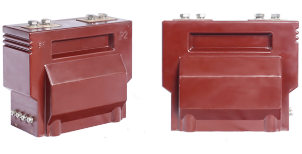
Product Shows

Working Principle
Operating on Faraday’s law of electromagnetic induction, the CT consists of a toroidal magnetic core and secondary windings. The primary conductor (busbar/cable) passes through the window and forms the primary turns. Primary current establishes alternating flux in the core, inducing EMF in the secondary winding and producing a standardized secondary current in the closed secondary circuit. Secondary burden (connected devices plus wiring losses) affects ratio/phase errors and protection performance (ALF behavior), therefore selection and verification should be performed under the specified burden and power-factor conditions. The cast-resin insulation system provides long-term dielectric stability and complete galvanic isolation between primary and secondary circuits.
System Application Position
- Medium Voltage Distribution: 6–10 kV indoor/outdoor switchgear, RMUs, and distribution panels for current sensing
- Energy Metering: Metering circuits configured with 0.2S/0.2/0.5 cores as required
- Protection Circuits: Overcurrent, differential, and distance protection schemes using 10P10/10P15 cores with ALF verification
- SCADA Integration: Current acquisition for monitoring systems (terminal allocation shall match the secondary wiring diagram)
- Outdoor & Pollution Areas: Outdoor substations, coastal/salt-mist, and industrial environments (selection based on creepage distance and IP rating)
Structural Overview
The fully enclosed epoxy cast-resin structure provides stable insulation performance and mechanical support, improving resistance to moisture and contamination. The post-type mounting arrangement supports compact installation within medium-voltage switchgear. Electrical clearance and creepage distance shall be confirmed according to the specific variant, pollution level, altitude, and dimensional drawings. For outdoor projects, selection should follow the project requirements for pollution level, creepage distance, and enclosure protection.
Model Designation

Code Explanation
- L — Current transformer (CT)
- Z — Post (support/pillar) type structure (indoor/outdoor applicability per variant definition)
- X / Z / ZW — Variant code (used to differentiate structure, creepage configuration, and outdoor adaptation)
- 10 — Voltage class (kV class)
Variant Differences
When specified with the same ratio, accuracy class combination, rated burdens, and Ith/Idyn values, LZX-10, LZZ-10, and LZZW-10 are electrically equivalent. Engineering differences are mainly related to structure and environmental configuration:
- LZX-10: General-purpose post-type design for common indoor/outdoor applications (standard creepage configuration)
- LZZ-10: Fully enclosed cast-resin variant suited for compact indoor switchgear and enhanced terminal protection
- LZZW-10: Outdoor-enhanced configuration, typically with increased creepage distance and improved pollution adaptation for severe environments
Service Conditions
The LZX-10, LZZ-10, and LZZW-10 series are designed for operation under the following conditions (conditions beyond these limits shall be declared and confirmed at the ordering stage):
- Installation environment: Indoor and outdoor installation
- Altitude: ≤ 1000 m above sea level (higher altitude requires insulation correction and engineering confirmation)
- Ambient temperature: −25 °C to +40 °C
- Relative humidity: ≤ 90% at +20 °C reference temperature
- Environmental conditions: Free from explosive/flammable media; avoid long-term severe vibration or mechanical shock; for outdoor projects, confirm IP rating and pollution requirements
- Pollution level: LZZW-10 is intended for higher pollution conditions (creepage distance per drawings/nameplate)
Construction
Construction Design
- Structure: Post-type configuration for 10 kV indoor/outdoor switchgear
- Insulation: Fully enclosed epoxy cast-resin insulation for stable dielectric performance and moisture resistance
- Core: Toroidal core with silicon-steel laminations to support specified accuracy and reduce losses
- System: Electromagnetic coupling with complete primary/secondary isolation for metering and protection sampling
- Environmental protection: Outdoor applications configured per variant IP rating and creepage distance
The cast-resin structure reduces the impact of humidity and contamination on insulation and provides mechanical fixation for the core and windings under long-term service conditions.
Windings & Terminal Marking

- Primary terminals: P1 / P2
- Secondary terminals (Group 1): 1S1 / 1S2
- Secondary terminals (Group 2): 2S1 / 2S2
Terminal markings follow CT polarity conventions per IEC 61869 and GB/T 20840. Under normal operating conditions, the reference current direction is defined from P1 to P2. Secondary wiring and terminal allocation shall match the secondary circuit diagram, and shall be implemented with one-point grounding and maintenance shorting provisions per the project safety rules.
Technical Data
This section provides selection-oriented technical data for preliminary configuration. Final acceptance shall be based on nameplate values, factory test reports, and project technical agreement.
Definitions: Accuracy class combination indicates the available metering/protection cores in one CT (each core operates independently in a multi-core configuration).
Burden: Rated output (VA) is specified per secondary core under the defined power-factor condition and shall cover relay/meter burden plus wiring losses.
Short-circuit ratings: Ith is the rated short-time thermal current (1 s). Idyn is the rated dynamic current (peak). Verification shall be consistent with the switchgear fault level and project requirements.
Data Reference
| Rated Primary Current (A) | 0.2S (VA) | 0.2 (VA) | 0.5 (VA) | 10P10 (VA) | 10P15 (VA) | Ith (kA/1s) | Idyn (kA) |
|---|---|---|---|---|---|---|---|
| 5 – 100 | 10 | 10 | 10 | 15 | 15 | 13.5 | 34 |
| 150 | 10 | 10 | 10 | 15 | 15 | 18 | 45 |
| 200 | 10 | 10 | 10 | 15 | 15 | 27 | 67.5 |
| 300 | 10 | 10 | 10 | 15 | 15 | 36 | 90 |
| 400 | 10 | 10 | 10 | 15 | 15 | 45 | 112.5 |
ALF vs Burden
The protection accuracy limit factor (ALF) varies with secondary burden. The curve illustrates the trend of protection accuracy capability under different burden conditions. Acceptance shall be based on nameplate data and test reports.

Standards & Normative References
| Standard | Title | Application |
|---|---|---|
| IEC 61869-1 | Instrument Transformers – Part 1: General Requirements | General requirements |
| IEC 61869-2 | Instrument Transformers – Part 2: Additional Requirements for Current Transformers | CT-specific requirements |
| GB/T 20840.1 | Instrument Transformers – Part 1: General Requirements | National standard aligned with the IEC 61869 framework |
| GB/T 20840.2 | Instrument Transformers – Part 2: Current Transformers | National CT requirements aligned with IEC 61869-2 |
| GB 1208 | Current Transformers | Legacy reference where required by the project specification |
| IEC 62271-1 | High-voltage switchgear and controlgear – Part 1: Common specifications | Switchgear common specifications reference where applicable |
| IEC 60085 | Electrical Insulation – Thermal Evaluation | Thermal evaluation reference |
| IEEE C57.13 | Standard Requirements for Instrument Transformers | Optional reference for North America projects |
Factory Test Compliance
- Routine tests per applicable IEC/GB requirements including:
- Polarity and terminal marking verification
- Ratio verification
- Accuracy verification per specified class and burden (0.2S, 0.2, 0.5, 10P10, 10P15)
- Secondary winding resistance measurement
- Dielectric tests per insulation coordination requirements:
- Power frequency withstand test (42 kV, 1 min)
- Lightning impulse withstand test (75 kV peak)
- Partial discharge test where specified by the project requirement
- Visual and dimensional inspection including marking and workmanship conformity
- Type and special tests as required by the project specification (temperature rise, short-circuit withstand verification, salt mist/UV/thermal cycling where applicable)
Installation & Dimensions
- Before installation, verify nameplate data (ratio, secondary current, accuracy class combination, rated burden, Ith/Idyn, insulation level) against the project documentation.
- Mount the CT using the designated fixing holes and ensure secure fastening; avoid applying uneven mechanical stress to the cast body.
- Primary conductor connection (busbar/bolted terminal) depends on the switchgear structure and variant drawing; maintain required clearances and creepage distances.
- Secondary wiring shall include anti-loosening and miswiring prevention measures, with provisions for maintenance shorting; implement one-point secondary grounding as required.
- After installation, perform circuit verification and necessary continuity/insulation checks per site procedures.
Outlines
LZZW-10 Dimensional Drawing

Note: Detailed outline and mounting drawings for LZX-10 and LZZ-10 shall follow the corresponding drawings and order technical documents.
Safety Notes
- The CT secondary circuit must remain closed during operation to prevent dangerous voltage on secondary terminals.
- Before removing meters/relays, short-circuit the secondary circuit to avoid open-circuit conditions.
- Implement one-point secondary grounding (e.g., S2 or designated grounding point) in accordance with applicable standards and project rules.
- Installation, commissioning, and maintenance shall be performed by qualified personnel only.
Ordering Information
When placing an order, the configuration shall be specified according to local grid requirements, applicable standards, and the project technical specification. The following information should be provided for engineering confirmation and production release:
- Model variant: LZX-10 / LZZ-10 / LZZW-10
- Rated primary current / transformation ratio: e.g., 100/5A, 200/5A
- Rated secondary current: 5 A (standard) or 1 A (upon request)
- Accuracy class combination: metering cores (0.2S/0.2/0.5) and protection cores (10P10/10P15), including number of cores
- Rated burden: VA per secondary core (10 VA / 15 VA or per project requirement)
- Short-circuit ratings: Ith (1 s) and Idyn (peak) requirement and switchgear fault level
- Installation environment: indoor/outdoor, pollution level, altitude, IP rating requirements
How to Select
- Define primary current and ratio based on feeder/load rating and operating range, considering metering/protection requirements.
- Select the variant based on installation constraints and environment: LZZ-10 for compact indoor switchgear, LZZW-10 for outdoor/high pollution conditions, LZX-10 for common indoor/outdoor use.
- Define accuracy classes and core quantity by allocating separate cores for metering and protection; verify protection performance against ALF and system fault levels.
- Calculate total secondary burden (VA) as the sum of connected device burden plus wiring losses (dependent on cable length and cross-section), ensuring it does not exceed the rated burden.
- Verify Ith/Idyn against the system fault level to ensure sufficient thermal and dynamic withstand capability.
If the project requires partial discharge limits, terminal arrangement constraints, documentation language, third-party witnessing, or additional certificates, specify them at the ordering stage and include them in the technical agreement.