Product Overview
Functional Definition
The JZZBJ9-10(A.B.C) series current transformers are precision electromagnetic instruments designed for accurate current measurement, energy metering, and relay protection applications in medium-voltage AC power systems. These transformers utilize electromagnetic induction principles to provide galvanically isolated secondary current signals proportional to primary current.
Key Ratings
| Item | Specification (per order / nameplate) |
|---|---|
| System voltage class | 10 kV class (indoor switchgear and distribution applications) |
| Rated frequency | 50 Hz (60 Hz available upon request) |
| Rated secondary current | 1 A or 5 A |
| Accuracy classes | Metering and/or protection cores as specified (e.g., 0.2S / 0.5, 10P10) |
| Rated burden | Per core/winding as specified (VA) |
| Burden power factor | cosφ = 0.8 (lagging) unless otherwise specified by the project standard |
| FS / ALF (where specified) | Metering security factor (FS) and protection accuracy limit factor (ALF) per ordered specification |
| Short-circuit withstand | Ith (1 s) and Idyn (peak) as specified |
| Insulation level | Per applicable standard and project specification |
| Applicable standards | IEC 61869-1 / IEC 61869-2; GB/T 20840.1 / 20840.2; GB 1208-1997; GB 5583-85 (PD where specified) |
| Mechanical variants | LZZBJ9-10A / LZZBJ9-10B / LZZBJ9-10C |
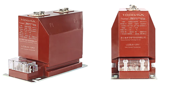
Product Shows

Working Principle
Operating on Faraday’s law of electromagnetic induction, the transformer features a toroidal magnetic core with primary conductor passing through the aperture and secondary windings wound around the core. The magnetic flux generated by primary current induces proportional voltage in the secondary winding, delivering standardized output current through connected burden.
System Application Position
- Medium Voltage Distribution: 6-10kV switchgear and distribution panels
- Energy Metering: Revenue-grade electricity measurement systems
- Protection Circuits: Overcurrent, differential, and distance protection schemes
- SCADA Integration: Supervisory control and data acquisition systems
Structural Overview
Epoxy resin cast construction with fully-enclosed design ensures superior insulation performance, moisture resistance, and mechanical strength. The post-type mounting configuration provides compact installation in constrained switchgear environments while maintaining excellent electrical clearance and creepage distances.
Model Designation

Code Explanation
- L — Current transformer (CT)
- Z — Indoor support (pillar) type
- Z — Cast-resin (epoxy) insulated, fully enclosed structure
- B — Protection configuration available (metering/protection application
- J — Reinforced design
- 9 — Design code (platform/iteration)
- 10 — Voltage class (kV)
- A / B / C — Mechanical variant code (installation/structure differences)
Variant Differences
LZZBJ9-10A, LZZBJ9-10B, and LZZBJ9-10C are electrically equivalent when specified with the same ratio, accuracy classes, burdens, and Ith/Idyn. The differences between A/B/C variants are primarily mechanical and installation-related to match different switchgear layouts and mounting constraints.
Service Conditions
The LZZBJ9-10 series current transformers are designed for indoor operation under normal service conditions in medium-voltage power systems.
- Installation environment: Indoor installation only
- Altitude: Not exceeding 1000 m above sea level (higher altitude shall be specified for engineering confirmation)
- Ambient temperature: −5 °C to +40 °C
- Relative humidity: Daily average ≤ 95%, monthly average ≤ 90% (at +20 °C reference)
- Environmental conditions: Free from corrosive gases or vapors; free from explosive or flammable media; no severe vibration, mechanical shock, or impact
Construction
Construction Design
- Structure: Support (post) type for indoor switchgear
- Insulation: Fully enclosed epoxy resin cast insulation
- Core: Ring-type magnetic core design
- System: Integrated primary and secondary insulation system
The epoxy resin casting provides stable insulation properties and resistance to moisture, contamination, and aging for long-term indoor service.
Windings & Terminal Marking
- Primary terminals: P1 / P2
- Secondary terminals (Group 1): 1S1 / 1S2
- Secondary terminals (Group 2): 2S1 / 2S2

Terminal markings follow standard CT polarity conventions. Under normal operating conditions, the reference current direction is defined from P1 to P2. Correct terminal identification shall be observed to ensure metering and protection performance.
Technical Data
This section provides selection-oriented technical data for the LZZBJ9-10 (A/B/C) series indoor, cast-resin current transformer used in 10 kV class AC systems (50 Hz). Data shown below is intended for preliminary selection of accuracy class combinations, rated burdens, and short-circuit withstand capability.
Definitions: Accuracy class combination indicates available metering/protection cores in one CT (multi-core configuration may apply). Rated output (VA) is specified per secondary core. Ith is the rated short-time thermal current (typically 1 s). Idyn is the rated dynamic current (peak).
Notation: Ith/Idyn may be expressed as kA or as multiples of rated primary current (×In) depending on configuration; acceptance shall be based on nameplate values and the factory test report.
Data Reference
| Rated Primary Current (A) |
Accuracy Class | Rated Output (VA) |
Short-time Thermal Current (Ith) |
Rated Dynamic Current (Idyn) |
|---|---|---|---|---|
| 5–100 | 0.2S / 10P10 | 10 / 15 | 150 × In | 375 × In |
| 150–200 | 0.2S / 0.5 / 10P10 | 10 / 15 / 15 | 21.5 kA | 54 kA |
| 300–400 | 0.5 / 10P10 | 10 / 15 | 31.5 kA | 80 kA |
| 500–600 | 0.2 / 10P10 | 10 / 15 | 45 kA | 112.5 kA |
| 800 | 0.2S / 10P10 0.2S / 0.5 / 10P10 0.5 / 10P10 0.2 / 10P10 |
10 / 15 10 / 10 / 15 10 / 15 10 / 15 |
63 kA | 130 kA |
| 1000 | 0.2S / 10P10 0.2S / 0.5 / 10P10 0.5 / 10P10 0.2 / 10P10 |
10 / 15 10 / 10 / 15 10 / 15 10 / 15 |
80 kA | 160 kA |
| 1200 | 0.2S / 10P10 0.2S / 0.5 / 10P10 0.5 / 10P10 0.2 / 10P10 |
10 / 15 10 / 10 / 15 10 / 15 10 / 15 |
80 kA | 160 kA |
| 1500 | 0.2S / 10P10 0.2S / 0.5 / 10P10 |
10 / 15 10 / 10 / 15 |
100 kA | 160 kA |
| 2000 | 0.5 / 10P10 0.2 / 10P10 |
10 / 15 10 / 15 |
100 kA | 160 kA |
Application Scenarios
Primary Applications
- Medium-voltage switchgear: Ring main units (RMU), metal-clad switchgear, load break switch panels, circuit breaker panels, motor control centers
- Metering and revenue collection: Electricity meters (including Class 0.2S applications), power quality monitoring, energy management and SCADA integration
- Protection relay systems: Overcurrent protection, differential schemes, feeder protection, motor protection and monitoring
- Industrial power distribution: Manufacturing power monitoring, process automation, critical load monitoring, energy efficiency optimization
Installation Environments
| Environment Type | Characteristics | Engineering Considerations |
|---|---|---|
| Indoor substations | Controlled environment, minimal contamination | Standard configuration suitable under normal service conditions |
| Industrial plants | Possible dust, vibration, and chemical exposure | Specify vibration level and contamination conditions; confirm installation clearances and maintenance access |
| Coastal / high humidity | High humidity and salt fog, risk of condensation | Specify humidity/condensation control and pollution conditions as project requirements; confirm creepage/clearance compliance |
| High dust environments | Dust accumulation and increased surface contamination risk | Specify pollution conditions and cleaning/inspection plan; confirm installation spacing and cable routing |
| High altitude sites | Reduced air density affecting insulation performance | Specify altitude at ordering stage for insulation coordination confirmation |
Standards & Normative References
| Standard | Title | Application |
|---|---|---|
| IEC 61869-1 | Instrument Transformers – Part 1: General Requirements | General requirements |
| IEC 61869-2 | Instrument Transformers – Part 2: Additional Requirements for Current Transformers | CT-specific requirements |
| GB/T 20840.1 | Instrument Transformers – Part 1: General Requirements | National standard (aligned with IEC 61869 framework) |
| GB/T 20840.2 | Instrument Transformers – Part 2: Current Transformers | National CT requirements (aligned with IEC 61869-2) |
| GB 1208-1997 | Current Transformers | National CT standard where specified by the project |
| GB 5583-85 | Partial Discharge Level Requirements | Partial discharge requirements where specified by the project |
| IEEE C57.13 | Standard Requirements for Instrument Transformers | Optional (North America project reference) |
| IEC 60068-2-17 | Environmental Testing – Salt Mist | Optional (project-specific environmental validation) |
| IEC 60085 | Electrical Insulation – Thermal Evaluation | Optional (insulation thermal evaluation reference) |
Factory Test Compliance
- Routine tests per applicable IEC/GB requirements (including polarity/marking, ratio verification, and accuracy verification per specified class and burden)
- Dielectric tests per insulation coordination requirements and applicable standard
- Partial discharge test where specified by the project requirement
- Visual and dimensional inspection including marking and workmanship conformity
- Type and special tests as required by the project specification
Installation & Dimensions
- Outline dimensions and mounting details are provided in the dimensional drawings.
- The transformer shall be securely mounted using the designated fixing holes.
- Primary conductor connection may be made via busbar or bolted terminals, depending on the variant.
- Adequate clearance shall be maintained for insulation, heat dissipation, and maintenance access.
Outlines
LZZBJ9-10A

LZZBJ9-10B

LZZBJ9-10C

Safety Notes
- Secondary circuit must never be left open when the transformer is energized, as dangerous high voltage may appear across the secondary terminals.
- During inspection or maintenance, the secondary circuit shall be short-circuited before disconnecting any instruments.
- One point of the secondary circuit should be reliably grounded in accordance with applicable standards.
- All installation and maintenance work shall comply with local electrical safety regulations.
Ordering Information
When placing an order, the required configuration shall be specified according to the local grid requirements, applicable standards, and project technical specification. The following parameters shall be clearly stated for technical confirmation and production release:
- Rated primary current / transformation ratio
- Rated secondary current (1 A or 5 A)
- Application and accuracy requirements (metering and/or protection accuracy class combination)
- Rated burden (VA) for each secondary core/winding
- Short-circuit withstand requirements: Ith (1 s) and Idyn (peak)
Selection Guidance
1: Determine rated primary current (Ip) based on feeder/load rating and expected operating range.
2: Select metering and/or protection accuracy requirements (e.g., 0.2S / 0.5 for metering; 10P10 for protection).
3: Confirm rated burden (VA) for each secondary circuit based on connected meters/relays and wiring losses.
4: Verify short-circuit withstand capability (Ith/Idyn) against the switchgear fault level.
If local utility or project requirements apply (e.g., insulation level, partial discharge limit, terminal arrangement, mounting constraints, documentation language, or required certificates), specify them at the ordering stage. Special configurations shall be confirmed by technical agreement and final data sheet prior to production.