Product Overview
Functional Definition
The LZZW-35 Epoxy Resin Cast Current Transformer are precision electromagnetic instruments designed for accurate current measurement, energy metering, and relay protection applications in 35 kV class outdoor AC power systems. These transformers utilize electromagnetic induction principles to provide galvanically isolated secondary current signals proportional to primary current. The fully enclosed epoxy resin cast structure ensures superior outdoor weatherability and insulation performance.
Key Ratings Snapshot
| Item | Specification (per order / nameplate) |
|---|---|
| System voltage class | 35 kV class (outdoor distribution and substation applications) |
| Rated frequency | 50 Hz or 60 Hz |
| Rated secondary current | 5 A |
| Accuracy classes | Metering and/or protection cores as specified (e.g., 0.2 / 0.2S / 0.5 / 0.5S, 10P10 / 10P15) |
| Rated burden | Per core/winding as specified (VA): 10-15 VA typical |
| Burden power factor | cosφ = 0.8 (lagging) unless otherwise specified by the project standard |
| FS / ALF (where specified) | Metering security factor (FS) and protection accuracy limit factor (ALF) per ordered specification |
| Short-circuit withstand | Ith (1 s): 13.5-40 kA; Idyn (peak): 34-100 kA (per rated primary current) |
| Insulation level | 40.5 / 95 / 185 kV (Um / Up / Ud) |
| Partial discharge | Compliant with GB1208-2006 and IEC 61869 requirements |
| Applicable standards | IEC 61869-1 / IEC 61869-2; GB/T 20840.1 / 20840.2; GB 1208-2006; IEC 185 |
| Installation type | Outdoor, post-mounted, fully enclosed epoxy resin structure |
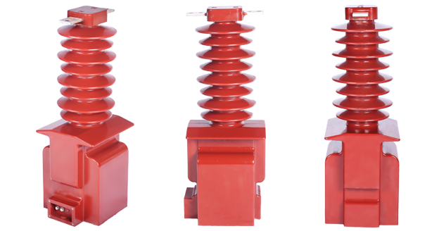
Product Shows
 Thomas Electric")
Working Principle
Operating on Faraday’s law of electromagnetic induction, the transformer features a toroidal magnetic core with primary conductor passing through the aperture and secondary windings wound around the core. The magnetic flux generated by primary current induces proportional voltage in the secondary winding, delivering standardized 5 A output current through connected burden. The epoxy resin encapsulation provides complete environmental protection while maintaining electromagnetic performance.
System Application Position
- 35 kV Distribution Networks: Outdoor substations and distribution systems
- Energy Metering: Revenue-grade electricity measurement for utility billing
- Protection Circuits: Overcurrent, differential, earth fault, and distance protection schemes
- SCADA Integration: Real-time current monitoring and data acquisition systems
- Outdoor Installations: Pole-mounted and outdoor switchgear applications
Structural Overview
Fully enclosed epoxy resin cast construction provides superior outdoor weatherability, moisture resistance, UV stability, and mechanical strength. The post-type mounting configuration enables outdoor installation while maintaining excellent electrical clearance and creepage distances. Internal components are hermetically sealed against environmental contamination, ensuring long-term reliability in harsh outdoor conditions including high pollution zones.
Model Designation
Model Code Explanation
 Thomas Electric")
- L — Current transformer (CT)
- Z — Post (pillar) type mounting structure
- Z — Cast-resin (epoxy) insulated, fully enclosed structure
- W — Outdoor installation type
- 35 — Voltage class (kV)
Service Conditions
The LZZW-35 series current transformers are designed for outdoor operation under specified environmental conditions in 35 kV power systems.
- Installation environment: Outdoor installation with appropriate weatherproofing
- Altitude: Not exceeding 1000 m above sea level (higher altitude configurations available upon specification)
- Ambient temperature: −25 °C to +40 °C (extended range to −40 °C available)
- Relative humidity: Daily average ≤ 95%, monthly average ≤ 90%
- Environmental conditions: Pollution level IV capability; free from corrosive gases, explosive media, or severe mechanical vibration
- Seismic resistance: Suitable for seismic intensity zones per applicable codes
Construction
Construction Design
- Structure: Post (pillar) type for outdoor mounting
- Insulation: Fully enclosed epoxy resin cast insulation system
- Core: High-permeability toroidal magnetic core
- Environmental sealing: Complete hermetic sealing against moisture and contamination
- UV resistance: Weatherproof epoxy formulation for long-term outdoor exposure
- Creepage distance: Enhanced for pollution level IV environments
The one-piece epoxy resin casting provides integral primary-to-secondary insulation, mechanical support, and environmental protection. Internal core and winding assemblies are completely encapsulated, eliminating moisture ingress and contamination risks throughout the service life.
Windings & Terminal Marking
 Thomas Electric")
- Primary terminals: P1 / P2
- Secondary terminals (Core 1): 1S1 / 1S2
- Secondary terminals (Core 2): 2S1 / 2S2
Terminal markings follow IEC 61869 and GB standards polarity conventions. Reference current direction flows from P1 to P2. Correct terminal identification is mandatory for proper metering accuracy and protection system coordination. All terminals are suitable for outdoor termination with weather-resistant connections.
Technical Data
This section provides selection-oriented technical data for the LZZW-35 fully enclosed, cast-resin current transformer used in 35 kV class outdoor AC systems (50 Hz / 60 Hz). Data shown below is intended for preliminary selection of accuracy class combinations, rated burdens, and short-circuit withstand capability.
Definitions: Accuracy class combination indicates available metering/protection cores in one CT (multi-core configuration). Rated output (VA) is specified per secondary core. Ith is the rated short-time thermal current (1 s duration). Idyn is the rated dynamic current (peak withstand).
Notation: All parameters subject to verification against nameplate values and factory test report. Selection must account for system fault level and protection coordination requirements.
Data Reference
| Rated Primary Current (A) |
Accuracy Class Combination |
Rated Output (VA) | Short-Time Thermal Current (ka/s) |
Rated Dynamic Current (kA) |
||||
|---|---|---|---|---|---|---|---|---|
| 0.2s | 0.2 | 0.5 | 10p10 | 10p15 | ||||
| 5-100 | 0.2 0.2S 0.5 0.5S 10P10 10P15 |
10 | 10 | 15 | 15 | 10 | 13.5 | 34 |
| 150 | 18 | 45 | ||||||
| 200 | 27 | 67.5 | ||||||
| 300 | 30 | 75 | ||||||
| 400 | 36 | 90 | ||||||
| 500 | 40 | 1001In | ||||||
| 600 | N/A | N/A | ||||||
| 750-1000 | N/A | N/A | ||||||
Standards & Normative References
| Standard | Title | Application |
|---|---|---|
| IEC 61869-1 | Instrument Transformers – Part 1: General Requirements | General requirements for instrument transformers |
| IEC 61869-2 | Instrument Transformers – Part 2: Additional Requirements for Current Transformers | CT-specific design and testing requirements |
| IEC 185 | Current Transformers (historical reference) | Legacy CT standard reference |
| GB/T 20840.1 | Instrument Transformers – Part 1: General Requirements | National standard (harmonized with IEC 61869-1) |
| GB/T 20840.2 | Instrument Transformers – Part 2: Current Transformers | National CT requirements (harmonized with IEC 61869-2) |
| GB 1208-2006 | Current Transformers | National CT standard for design and acceptance |
| GB 311.1 | Insulation Co-ordination for High-Voltage Systems | Insulation level determination and verification |
Factory Test Compliance
- Routine tests per IEC 61869 and GB standards: ratio verification, polarity, accuracy at specified burden, insulation resistance
- Dielectric tests per insulation coordination class and system voltage
- Partial discharge test per GB 1208-2006 requirements (≤10 pC typical)
- Visual and dimensional inspection including terminal marking and nameplate verification
- Type tests (temperature rise, short-circuit withstand, environmental exposure) per project specification
Installation & Dimensions
- Installation shall be performed by qualified personnel in accordance with local electrical codes and utility requirements
- Primary busbar or cable connection requires proper mechanical support and electrical clearance
- Secondary wiring shall use weather-resistant cable with proper strain relief
- Grounding terminal must be connected to station ground grid per applicable standards
- Maintain specified creepage and clearance distances for outdoor pollution environment
Outline
 Thomas Electric")
Dimensional drawings available upon request based on specific rated primary current and mechanical configuration.
Safety Notes
- Secondary circuit must never be open when the transformer is energized (dangerous high voltage hazard)
- During inspection or maintenance, short-circuit the secondary before disconnecting any instruments or wiring
- One point of the secondary circuit shall be reliably grounded per IEC and GB standards
- All work shall comply with applicable electrical safety regulations and utility procedures
- Outdoor installations require periodic inspection for contamination, terminal integrity, and weather damage
Ordering Information
When placing an order, the required configuration shall be specified according to system requirements, applicable standards, and project technical specification. The following parameters shall be clearly stated for technical confirmation and production release:
- Rated primary current / transformation ratio
- Rated secondary current (5 A standard)
- Application and accuracy requirements (metering and/or protection accuracy class combination)
- Rated burden (VA) for each secondary core/winding
- Short-circuit withstand requirements: Ith (1 s) and Idyn (peak)
- Environmental conditions: Pollution level, ambient temperature range, altitude
- Special requirements: Extended creepage distance, seismic rating, specific test requirements
Selection Guidance
1. Determine rated primary current (Ip) based on maximum continuous load and future expansion requirements
2. Select metering and/or protection accuracy classes per utility metering standards and protection relay specifications (e.g., 0.2S for revenue metering; 10P10 for overcurrent protection)
3. Calculate rated burden (VA) for each secondary circuit: sum of connected instrument burden plus estimated cable losses at rated secondary current
4. Verify short-circuit withstand (Ith/Idyn) against system maximum fault current and protection clearing time
5. Specify pollution level and environmental conditions for appropriate creepage distance selection
Custom configurations available for non-standard ratios, extended temperature ranges, enhanced seismic requirements, or project-specific certifications. Technical review recommended for all applications—contact factory engineering for application support.