Visão Geral do Produto
Definição Funcional
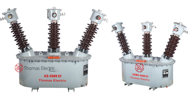
The JLS-35 is an outdoor, oil-immersed combined instrument transformer (metering box) integrating two single-phase fully-insulated VTs and two CTs in a sealed oil-filled enclosure. The VTs are connected in V/V, and the CTs are installed in series on phases A and C to provide isolated secondary voltage and current outputs for 35 kV-class metering and monitoring. The oil-immersed insulation system improves dielectric strength, heat dissipation, and weather resistance for outdoor service.
Principais Características Nominais
| Item | Specification (per order / nameplate) |
|---|---|
| System voltage class | 35 kV (outdoor metering and distribution applications) |
| Rated frequency | 50 Hz / 60 Hz |
| Configuration | 2 × single-phase voltage transformers (V/V connection) + 2 × current transformers |
| Voltage transformer connection | Three-phase V/V (open delta) configuration |
| Current transformer installation | Series-connected in phases A and C |
| Accuracy classes | 0.2 / 0.2S for metering cores (voltage and current) |
| Isolamento type | Oil-immersed with fully-insulated windings |
| Instalação environment | Para Exterior (weatherproof oil tank enclosure) |
| Moisture protection | Enhanced moisture barrier device on tank cover |
| Applicable standards | GB 20840.4-2015 (Combined IT); GB 20840.2-2014, GB 20840.1-2010 (CT); GB 20840.3-2013, GB 20840.1-2010 (VT) |
| Lightning protection | Surge arrester required within 1 meter of installation location |
Product Shows

Princípio de Funcionamento
Voltage Transformation: Two single-phase electromagnetic voltage transformers reduce the 35 kV primary voltage to standardized secondary voltages. Connected in V/V (open-delta), they provide three-phase line-to-line voltage signals for metering and monitoring circuits.
Current Transformation: The current transformers utilize toroidal or wound magnetic cores with primary conductor carrying load current and secondary windings providing proportional output current. Instalação in phases A and C enables comprehensive three-phase current metering when combined with the voltage signals.
Oil Isolamento System: Both voltage and current transformers are immersed in high-quality transformer oil within a sealed tank. The oil provides electrical insulation, heat dissipation, and environmental protection. The enhanced moisture barrier on the tank cover prevents ingress of atmospheric humidity, significantly extending service life.
Posição de Aplicação no Sistema
- Rural Distribuição Networks: Revenue-grade metering in rural 35 kV substations and distribution points
- Para Exterior Substations: Compact metering solutions for outdoor switchgear installations
- Industrial Facilities: High-voltage energy metering for factories, mills, and industrial parks
- Small Subestação Applications: Space-efficient combined metering in compact substation designs
- Active/Reactive Energy Medição: Simultaneous measurement of real and reactive power consumption
Visão Geral Estrutural
The JLS-35 features a compact rectangular oil tank housing all transformer components. The tank is fabricated from high-quality steel with weatherproof coating suitable for outdoor environments. Key structural features include:
- IInternal frame mounting of 2 VTs + 2 CTs
- Tanque cover with lifting lugs for handling
- Oil level indicator for visual inspection of oil fill status
- External earthing (ground) terminal
- Oil drain valve for maintenance and oil replacement procedures
- Enhanced moisture barrier device preventing water ingress
- Compact dimensions with reduced weight compared to legacy designs
Designação do Modelo

Explicação do Código do Modelo
- J — Combined instrument transformer (voltage + current)
- L — Current transformer component designation
- S — Oil-immersed (liquid-insulated) construction
- 35 — Voltage class (kV)
Full Designation: JLS-35 identifies this as a 35 kV class outdoor oil-immersed combined instrument transformer integrating voltage and current measurement functions in a single metering assembly.
Condições de Serviço
The JLS-35 combined instrument transformer is designed for outdoor installation under the following normal service conditions:
- Instalação environment: Para Exterior installation with direct weather exposure
- Altitude: Not exceeding 1000 m above sea level (higher altitude applications require engineering confirmation and possible derating)
- Ambient temperature: −25 °C to +40 °C (oil viscosity and insulation properties maintained across this range)
- Relative humidity: Daily average ≤ 95%, monthly average ≤ 90%
- Pollution level: Suitable for light to moderate pollution environments; heavy pollution areas may require enhanced external insulation
- Seismic conditions: Installations in seismic zones shall be confirmed during engineering design phase
- Environmental conditions: No corrosive gases or vapors that degrade oil or tank materials; no explosive atmosphere
Construção
Design de Construção
Overall Assembly:
- Enclosure: Weatherproof rectangular oil tank with corrosion-resistant coating
- Voltage Transformers: Two single-phase fully-insulated electromagnetic voltage transformers
- Current Transformers: Two electromagnetic current transformers with toroidal or wound core construction
- Isolamento Medium: High-quality transformer oil providing electrical insulation and thermal management
- Moisture Proteção: Enhanced barrier device on tank cover preventing atmospheric moisture ingress
Tanque Design Features:
- Seamless cover design with two lifting lugs for installation handling
- Oil level sight glass for visual oil quantity inspection
- Grounding terminal for protective earthing connection
- Oil drain valve for maintenance procedures
- Compact rectangular footprint optimizing space utilization
- Reduced overall weight compared to traditional combined transformer designs
Internal Configuration: Voltage and current transformer assemblies are securely mounted on internal framework within the oil tank. All high-voltage and low-voltage connections are made inside the sealed enclosure, with secondary terminals brought out through insulated bushings.
Enrolamentos & Marcação de Terminais

Transformador de Potencial Terminais:
- Primário terminals (Phase A PT): A / N or A / X (depending on configuration)
- Primário terminals (Phase C PT): C / N or C / X
- Secundário terminals (metering): a / n or a / x (Phase A); c / n or c / x (Phase C)
Transformador de Corrente Terminais:
- Primário terminals (Phase A CT): P1 / P2 (series connection in phase A conductor)
- Primário terminals (Phase C CT): P1 / P2 (series connection in phase C conductor)
- Secundário terminals (Phase A CT): 1S1 / 1S2
- Secundário terminals (Phase C CT): 2S1 / 2S2 (or designated core numbering per specification)
Terminal markings follow standard instrument transformer polarity and phasing conventions per GB 20840 series standards. Correct terminal identification is critical for proper metering accuracy and system integration.
Dados Técnicos
This section provides selection-oriented technical data for the JLS-35 outdoor oil-immersed combined instrument transformer for 35 kV class three-phase AC systems (50 Hz / 60 Hz). The data supports preliminary selection of voltage ratios, current ratios, accuracy classes, and burden requirements for rural grid, outdoor substation, and industrial metering applications.
Configuration Notes: The JLS-35 integrates two voltage transformers in V/V connection and two current transformers. Voltage ratios, current ratios, accuracy classes, and rated burdens are specified per individual transformer core/winding according to metering system requirements.
Data Reference
| Rated Primário Voltage (kV) |
Rated Secundário Voltage (V) |
Accuracy Class |
Rated Carga (VA) |
Conexão Type |
|---|---|---|---|---|
| 35 / √3 | 100 / √3 | 0.2 / 0.2S | 25 – 100 VA (per core) | V/V (two single-phase units) |
| 35 / √3 | 100 | 0.2 / 0.2S | 25 – 100 VA (per core) | Line-to-neutral equivalent (V/V configuration) |
| Other voltage ratios available upon request and engineering confirmation | ||||
| Rated Primário Current (A) |
Rated Secundário Current |
Accuracy Class |
Rated Carga (VA) |
Instalação Location |
|---|---|---|---|---|
| 5 – 1500 A | 1 A / 5 A | 0.2 / 0.2S | 2.5 – 20 VA (per core) | Phases A and C |
| Specific ratio and burden combinations subject to engineering confirmation | ||||
Normas & Normative References
| Standard | Title | Application |
|---|---|---|
| GB 20840.4-2015 | Instrument Transformers – Part 4: Combined Transformers | Combined transformer requirements (metering box compliance) |
| GB 20840.2-2014 | Instrument Transformers – Part 2: Additional Requirements for Current Transformers | CT component requirements |
| GB 20840.1-2010 | Instrument Transformers – Part 1: General Requirements | General requirements for all instrument transformers |
| GB 20840.3-2013 | Instrument Transformers – Part 3: Additional Requirements for Voltage Transformers | VT/PT component requirements |
| IEC 61869-1 | Instrument Transformers – Part 1: General Requirements | International reference (where specified by project) |
| IEC 61869-2 | Instrument Transformers – Part 2: Additional Requirements for Current Transformers | International CT reference |
| IEC 61869-3 | Instrument Transformers – Part 3: Additional Requirements for Voltage Transformers | International VT reference |
Factory Test Compliance
- Routine tests per GB 20840 series requirements:
- Polarity and terminal marking verification (VT and CT)
- Ratio verification at rated voltage/current
- Accuracy verification at specified burden and accuracy class
- Isolamento resistance measurement
- Dielectric tests:
- Power frequency withstand voltage test per insulation level
- Impulse voltage test (where specified)
- Oil quality verification:
- Dielectric breakdown voltage of transformer oil
- Moisture content and contamination analysis
- Visual and dimensional inspection:
- Tanque integrity, coating quality, and weatherproofing verification
- Nameplate data accuracy and legibility
- Accessory functionality (oil level gauge, drain valve, grounding terminal)
- Type and special tests as required by project specification or utility standards
Instalação & Dimensões
Instalação Requirements
- Foundation: The transformer shall be mounted on a stable, level concrete foundation or steel platform capable of supporting the total weight including oil fill.
- Clearances: Adequate electrical clearances shall be maintained per applicable standards and local electrical codes. Minimum clearances for maintenance access, oil inspection, and equipment replacement shall be confirmed during site design.
- Lightning Proteção: A zinc oxide surge arrester shall be installed within 1 meter of the transformer to provide effective overvoltage protection. Arrester rating and grounding shall be coordinated with the system insulation level.
- Grounding: The tank grounding terminal shall be connected to the substation ground grid using properly sized grounding conductor. Both voltage transformer and current transformer secondary circuits shall have one point reliably grounded per applicable standards.
- Primário Connections: High-voltage primary connections shall be made via cable lugs, busbar terminals, or other approved methods suitable for 35 kV class insulation.
- Secundário Wiring: Secundário circuits shall be routed to metering equipment using properly sized control cable. Cable screens shall be grounded at one point only to prevent circulating currents.
Outlines

Nota: Dimensional drawings show overall tank dimensions, mounting hole locations, terminal positions, and accessory placement. Refer to certified dimensional drawings supplied with each unit for as-built dimensions.
Notas de Segurança
- CT Secundário Open-Circuit Hazard: Opening CT secondary circuits under load creates dangerous high voltage across secondary terminals and may damage the transformer. Always short-circuit CT secondaries before disconnecting meters or relays.
- VT Secundário Proteção: Voltage transformer secondary circuits shall be protected by appropriately rated fuses or miniature circuit breakers to prevent winding damage under fault conditions.
- Grounding: One point of each secondary circuit (CT and VT) shall be reliably grounded to prevent dangerous voltages in case of insulation failure.
- Oil Handling: Transformador oil is flammable and shall be handled per local environmental and fire safety regulations. Oil replacement or top-up operations shall be performed by qualified personnel only.
- Lightning Proteção: Failure to install surge arresters exposes the transformer to lightning and switching overvoltages which may cause catastrophic insulation failure.
- Qualified Personnel: All installation, commissioning, maintenance, and repair work shall be performed by qualified electrical personnel in accordance with local electrical safety regulations and utility standards.
Informações para Pedido
When placing an order for JLS-35 combined instrument transformers, the following technical parameters and project requirements shall be clearly specified to ensure correct configuration and compliance with system standards.
Optional Customization
- Special tank dimensions or mounting configurations
- Alternative tank materials or coatings for severe environments
- Additional secondary cores (metering + spare/auxiliary)
- Special terminal arrangements or cable gland types
- Language requirements for nameplate and documentation
- Witnessed testing or third-party certification requirements
Selection Guidance
Step 1 – Voltage Ratio Selection: Determine voltage transformer ratio based on system nominal voltage (typically 35 kV line-to-line) and required secondary voltage for metering equipment (typically 100 V or 100 / √3 V).
Step 2 – Current Ratio Selection: Select current transformer ratios based on anticipated maximum load current with sufficient margin for overload and future load growth. Ensure rated primary current is appropriate for continuous operation at expected load levels.
Step 3 – Classe de Precisão Confirmation: Specify 0.2 or 0.2S accuracy class based on revenue metering requirements and applicable utility standards. Class 0.2S provides tighter accuracy limits at low load currents.
Step 4 – Carga Calculation: Calculate total connected burden including energy meters, demand meters, transducers, and wiring resistance. Select rated burden with adequate margin above calculated burden to ensure accuracy compliance.
Step 5 – Environmental Verification: Confirm that standard service conditions match actual installation environment. Special configurations may be required for high altitude, extreme temperature, or heavy pollution environments.
For complex applications or non-standard requirements, technical consultation with factory engineering team is recommended prior to order placement.