Product Overview
Functional Definition
The JDZX10-3/6/10A(B) series voltage transformers (also designated REL-10) are single-phase electromagnetic induction instruments designed for accurate voltage measurement, energy metering, voltage control, and relay protection applications in medium-voltage AC power systems. These transformers utilize electromagnetic induction principles to provide galvanically isolated secondary voltage signals proportional to primary voltage. The series covers 3 kV, 6 kV, and 10 kV voltage classes with rated frequency of 50 Hz or 60 Hz, suitable for both non-grounded and neutral-grounded system configurations.
Key Ratings
| Item | Specification (per order / nameplate) |
|---|---|
| System voltage class | 3 kV / 6 kV / 10 kV class (indoor distribution applications) |
| Rated frequency | 50 Hz (60 Hz available upon request) |
| Rated voltage ratio | 3000/√3/100/√3/100/3 V, 6000/√3/100/√3/100/3 V, 10000/√3/100/√3/100/3 V |
| Accuracy classes | Metering: 0.2, 0.5, 1 | Protection: 6P |
| Rated burden | Variant A: 15-60 VA | Variant B: 25-90 VA (per accuracy class) |
| Burden power factor | cosφ = 0.8 (lagging) unless otherwise specified by the project standard |
| Limit output | Variant A: 150 VA | Variant B: 400 VA |
| Insulation level | 3 kV: 3.6/25/40 kV | 6 kV: 7.2/32/60 kV | 10 kV: 12/42/75 kV |
| Pollution degree | Class II per applicable standard |
| Applicable standards | IEC 61869-1 / IEC 61869-3; GB 1207-2006; GB 20840.1-2010 / GB 20840.3-2013 |
| Mechanical variants | JDZX10-3A/3B, JDZX10-6A/6B, JDZX10-10A/10B (equivalent to REL-10 series) |
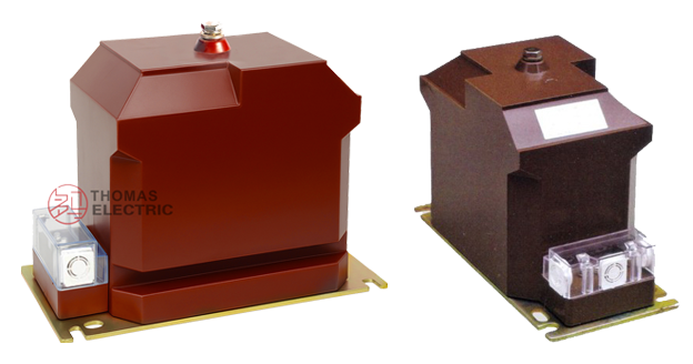
Product Shows

Working Principle
Operating on Faraday’s law of electromagnetic induction, the voltage transformer features a laminated magnetic core with primary winding connected to the high-voltage system and secondary winding(s) providing low-voltage output. The magnetic flux generated by primary voltage induces proportional voltage in the secondary winding, delivering standardized output voltage through connected burden. The transformer maintains accurate voltage transformation ratio and phase relationship for metering and protection applications.
System Application Position
- Medium Voltage Distribution: 3-10 kV switchgear and distribution panels
- Energy Metering: Revenue-grade electricity measurement systems
- Voltage Control: Automatic voltage regulation and monitoring systems
- Protection Circuits: Overvoltage, undervoltage, and directional protection schemes
- SCADA Integration: Supervisory control and data acquisition systems
Structural Overview
Epoxy resin cast construction with fully-enclosed design ensures superior insulation performance, moisture resistance, and mechanical strength. The integrated core-winding structure provides compact dimensions and lightweight characteristics. Three-way secondary terminal arrangement in enclosed terminal box enables flexible wiring configuration while maintaining excellent electrical clearance and creepage distances. The structure is suitable for both non-grounded and neutral-grounded system applications.
Model Designation

Model Code Explanation
- J — Voltage transformer (VT/PT)
- D — Single-phase configuration
- Z — Cast-resin (epoxy) insulated, fully enclosed structure
- X — Indoor installation type
- 10 — Design code (platform/iteration)
- 3 / 6 / 10 — Voltage class (kV)
- A / B — Output capacity variant code (A: standard capacity, B: enhanced capacity)
Variant Differences
Variant A (JDZX10-xA): Standard capacity configuration with rated outputs of 15 VA (0.2 class), 30 VA (0.5 class), 60 VA (1 class), 50 VA (6P class), and limit output of 150 VA. Suitable for typical metering and protection applications with moderate burden requirements.
Variant B (JDZX10-xB): Enhanced capacity configuration with rated outputs of 25 VA (0.2 class), 50 VA (0.5 class), 90 VA (1 class), 50 VA (6P class), and limit output of 400 VA. Designed for applications requiring higher burden capacity or multiple connected instruments.
Both A and B variants are electrically equivalent when specified with the same voltage ratio, accuracy classes, and insulation level. Selection between variants is based on total burden requirements of connected metering and protection devices including wiring losses.
Service Conditions
The JDZX10 series voltage transformers are designed for indoor operation under normal service conditions in medium-voltage power systems.
- Installation environment: Indoor installation only
- Altitude: Not exceeding 3000 m above sea level (higher altitude shall be specified for engineering confirmation)
- Ambient temperature: −5 °C to +40 °C
- Relative humidity: Not exceeding 65% at +20 °C reference temperature
- Pollution degree: Class II per applicable standard
- Environmental conditions: Free from corrosive gases or vapors; no explosive or flammable media; no severe vibration, mechanical shock, or impact
Construction
Construction Design
- Structure: Single-phase indoor type with integrated core-winding assembly
- Insulation: Fully enclosed epoxy resin cast insulation system
- Core: High-quality silicon steel laminated core design
- Windings: Primary and secondary windings integrated with core in single molding process
- Terminals: Secondary terminals housed in enclosed terminal box with three-way exit configuration
The epoxy resin casting provides stable insulation properties and resistance to moisture, UV radiation, contamination, and aging for long-term indoor service. Compact and lightweight construction facilitates installation in constrained switchgear environments.
Windings & Terminal Marking

- Primary terminals: A / X (or designated per project requirement)
- Secondary terminals (Metering winding): a / x
- Secondary terminals (Auxiliary winding): a1 / x1 (where applicable)
- Secondary terminals (Open delta winding): ad / xd (where applicable)
Terminal markings follow standard VT polarity conventions per IEC 61869 and GB 1207-2006. Under normal operating conditions, when primary terminal A is positive relative to X, secondary terminal a is positive relative to x. Correct terminal identification shall be observed to ensure metering and protection performance.
Technical Data
This section provides selection-oriented technical data for the JDZX10-3/6/10A(B) series indoor, cast-resin voltage transformer used in 3 kV, 6 kV, and 10 kV class AC systems (50 Hz or 60 Hz). Data shown below is intended for preliminary selection of voltage class, accuracy class combinations, rated burdens, and insulation levels.
Definitions: Accuracy class combination indicates available metering/protection accuracy classes in one VT (multi-winding configuration may apply). Rated output (VA) is specified per accuracy class and represents the burden at which the stated accuracy is maintained. Limit output represents maximum thermal capacity of the transformer.
Notation: Voltage ratio format “10000/√3/100/√3/100/3” indicates: primary rated voltage 10000V line-to-line (10000/√3 V line-to-neutral) with secondary windings providing 100V line-to-line (100/√3 V line-to-neutral) and 100V or 100/3V for auxiliary applications.
Data Reference
| Type | Rated Voltage Ratio (V) |
Frequency (Hz) |
Accuracy Class and Rated Output (VA) |
Limit Output (VA) |
Rated Insulation Level (kV) |
Remark | |||
|---|---|---|---|---|---|---|---|---|---|
| 0.2 | 0.5 | 1 | 6P | ||||||
| JDZX10-3A | 3000/√3/100/√3/100/3 | 50/60 | 15 | 30 | 60 | 50 | 150 | 3.6/25/40 | Same as REL10 |
| JDZX10-6A | 6000/√3/100/√3/100/3 | 15 | 30 | 60 | 50 | 150 | 7.2/32/60 | ||
| JDZX10-10A | 10000/√3/100/√3/100/3 | 15 | 30 | 60 | 50 | 150 | 12/42/75 | ||
| JDZX10-3B | 3000/√3/100/√3/100/3 | 25 | 50 | 90 | 50 | 400 | 3.6/25/40 | ||
| JDZX10-6B | 6000/√3/100/√3/100/3 | 25 | 50 | 90 | 50 | 400 | 7.2/32/60 | ||
| JDZX10-10B | 10000/√3/100/√3/100/3 | 25 | 50 | 90 | 50 | 400 | 12/42/75 | ||
Standards & Normative References
| Standard | Title | Application |
|---|---|---|
| IEC 61869-1 | Instrument Transformers – Part 1: General Requirements | General requirements for voltage transformers |
| IEC 61869-3 | Instrument Transformers – Part 3: Additional Requirements for Inductive Voltage Transformers | VT-specific requirements |
| GB 1207-2006 | Voltage Transformers | National standard for voltage transformers |
| GB 20840.1-2010 | Instrument Transformers – Part 1: General Requirements | National standard (aligned with IEC 61869 framework) |
| GB 20840.3-2013 | Instrument Transformers – Part 3: Voltage Transformers | National VT requirements (aligned with IEC 61869-3) |
| IEC 60071-1 | Insulation Co-ordination – Part 1: Definitions, Principles and Rules | Insulation coordination reference |
| IEC 60060-1 | High-voltage Test Techniques – Part 1: General Definitions and Test Requirements | High-voltage testing procedures |
| IEEE C57.13 | Standard Requirements for Instrument Transformers | Optional (North America project reference) |
Factory Test Compliance
- Routine tests per applicable IEC/GB requirements (including polarity/marking verification, voltage ratio verification, and accuracy verification per specified class and burden)
- Dielectric tests per insulation coordination requirements and applicable standard (power frequency withstand voltage, lightning impulse withstand voltage)
- Partial discharge test where specified by the project requirement (typically ≤10 pC per IEC 61869-1)
- Temperature rise test to verify thermal performance under rated and limit output conditions
- Visual and dimensional inspection including marking and workmanship conformity
- Type and special tests as required by the project specification (short-circuit withstand, ferroresonance performance where applicable)
Installation Environments
- Outline dimensions and mounting details are provided in the dimensional drawings.
- The transformer shall be securely mounted using the designated fixing holes with appropriate hardware.
- Primary connection shall be made to designated terminals with appropriate clearance and creepage distances maintained.
- Secondary wiring shall be routed through the terminal box with three-way exit options for flexible cable management.
- Adequate clearance shall be maintained for insulation, heat dissipation, and maintenance access per applicable standards.
- For grounded neutral systems, grounding connection shall be made per system grounding practice and local regulations.
Outlines

JDZX10-10A, JDZX10-10B, Rel-10 Voltage Transformers Installation Outline.

Connection Diagrams
Safety Notes
- Voltage transformer secondary circuits shall be fused with appropriate rating to prevent thermal overload from fault conditions.
- One point of the secondary circuit should be reliably grounded in accordance with applicable standards and local practice.
- Before connecting burden devices, verify voltage ratio and polarity to prevent incorrect metering or protection operation.
- During installation or maintenance, verify primary circuit is de-energized and appropriate safety procedures are followed.
- All installation and maintenance work shall comply with local electrical safety regulations and utility requirements.
Ordering Information
When placing an order, the required configuration shall be specified according to the local grid requirements, applicable standards, and project technical specification. The following parameters shall be clearly stated for technical confirmation and production release:
- Voltage class and voltage ratio (e.g., 10 kV class, 10000/√3/100/√3/100/3 V)
- Rated frequency (50 Hz or 60 Hz)
- Application and accuracy requirements (metering and/or protection accuracy class combination)
- Rated burden (VA) for each accuracy class / secondary winding
- Variant selection (A: standard capacity, B: enhanced capacity)
- Insulation level requirements (if different from standard)
- Winding configuration (number of secondary windings and their applications)
If local utility or project requirements apply (e.g., specific winding configurations, terminal arrangement, ferroresonance suppression, mounting constraints, documentation language, or required certificates), specify them at the ordering stage. Special configurations shall be confirmed by technical agreement and final data sheet prior to production.