Product Overview
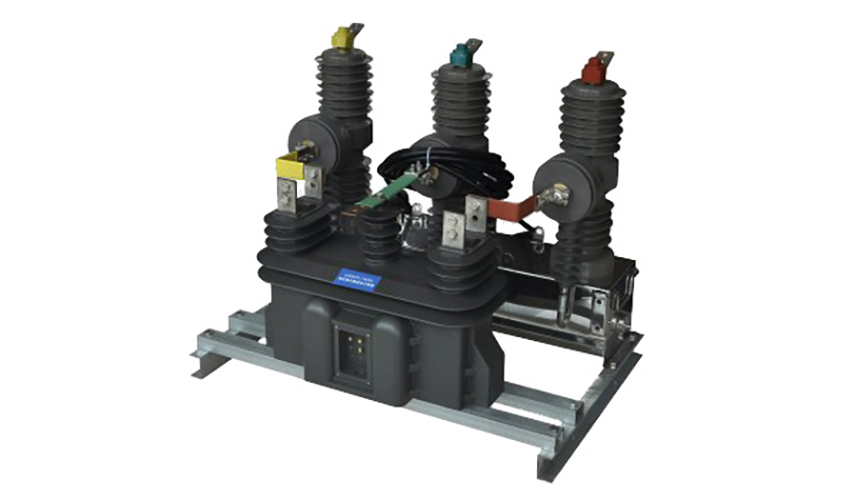
ZWJ-12 series high-voltage prepaid metering boxes are integrated load control and metering devices designed for 10 kV, 50 Hz power distribution systems with capacity up to 5000 kVA. The integrated design combines vacuum circuit breaker (VCB), voltage transformer (PT), and current transformer (CT) in a fully enclosed configuration to provide comprehensive prepaid metering, load control, and protection functions.
Key Ratings
| Item | Specification |
|---|---|
| System voltage class | 10 kV (6-35 kV available upon request) |
| Rated frequency | 50 Hz |
| Rated current | 630 A (400-1250 A configurable) |
| Short-circuit breaking capacity | 20 kA / 3s (up to 31.5 kA available) |
| Insulation level | 12/42/75 kV (Um/AC/LI per IEC 60071-1) |
| Ambient temperature range | -40°C to +55°C (extended -45°C to +60°C available) |
| Protection rating | IP4X (indoor), IP54 (outdoor option) |
| Metering accuracy | Class 0.5S (0.2S high-precision available) |
| Control voltage | AC/DC 110-240V (24-48V DC available) |
| Communication interface | GSM/GPRS, RS485, Ethernet (optional) |
| Installation type | Pole-mounted or wall-mounted configuration |
| Applicable standards | IEC 62271-200, GB 17201-2007, GB 1984-2003 |
Working Principle
The ZWJ-12 operates on integrated electromagnetic principles combining three core functions: vacuum circuit breaker (VCB) operation, voltage transformer (PT) configuration, and current transformer (CT) integration. The VCB utilizes vacuum interrupter technology with copper-chromium contacts for reliable interruption of fault currents up to 31.5 kA. Dual voltage transformers provide both metering and control power functions with open-delta configuration enabling ground fault detection. Three-phase current transformers enable precise energy measurement (Class 0.5S accuracy) and overcurrent protection (Class 10P15).
Application
The ZWJ-12 series is suitable for rural grid applications, urban distribution networks, industrial facilities, and remote locations. It provides effective revenue protection through automatic disconnection when credit is exhausted, enables remote load control for demand response programs, and supports smart grid integration as a foundation for advanced metering infrastructure (AMI) deployment. The integrated design eliminates separate components, reducing installation complexity and improving system reliability for utility operators.
Structural Overview
The ZWJ-12 features a compact, fully enclosed design integrating all components into a single weather-resistant enclosure constructed from 304 stainless steel or hot-dip galvanized steel (≥80μm zinc coating). The modular construction allows for easy maintenance and component replacement without complete system shutdown. Internal compartments are separated to prevent interference between high-voltage and low-voltage circuits, ensuring safety and reliability in outdoor environments with IP4X/IP54 protection ratings.
Model Designation
The model designation follows international standardization practices for electrical equipment identification per IEC 61869 and GB/T 17201-2007 standards.
Code Explanation
Z — Combined instrument transformer (metering box)
W — Outdoor installation type
J — Prepaid metering function
12 — Voltage class designation (10 kV system)
Construction
The ZWJ-12 construction design incorporates several key engineering principles for safety, reliability, and ease of maintenance. All high-voltage components are housed in sealed compartments accessible only with proper safety procedures, while low-voltage control and communication components are housed in separate, easily accessible compartments.
Construction Design
Material Selection
- Enclosure: 304 stainless steel or hot-dip galvanized steel (≥80μm zinc coating)
- Internal components: Copper-chromium alloy for VCB contacts, silicon steel for magnetic cores
- Insulation materials: Epoxy resin with UV stabilizers for outdoor durability
- Sealing compounds: Silicone-based gaskets resistant to temperature extremes (-50°C to +120°C)
Mechanical Design
- Structural integrity: Designed to withstand 0.3g seismic loading per IEC 60068-2-57
- Thermal management: Natural convection cooling with thermal monitoring
- Cable management: Integrated cable trays and strain relief provisions
- Access provisions: Lockable doors with safety interlocks for maintenance access
Windings & Terminal Marking
Primary conductors: Three-phase cables pass through integrated busbar structure
Secondary terminals: Clearly marked K1/K2 for CT, A/X for PT
Control wiring: Standardized terminal blocks with protective covers
Communication interfaces: RJ45 connector for Ethernet, GSM antenna port
All windings are designed and tested per IEC 61869 standards with appropriate insulation coordination for the specified voltage class. Terminal markings follow international standards to ensure proper connection and polarity verification during installation.
Service Conditions
The ZWJ-12 series is designed for reliable operation under normal service conditions in medium-voltage power distribution systems per IEC 62271-1 requirements.
Environments
Installation environments: Rural areas, urban settings, industrial sites, coastal regions, and high-altitude locations.
Environmental adaptations: Extended temperature range components, humidity protection with desiccant breathers, enhanced corrosion resistance with stainless steel construction, UV-stabilized materials, and dust/sand protection with enhanced sealing.
Technical Data
This section provides technical data for the ZWJ-12 series high-voltage prepaid metering boxes designed for 10 kV AC systems (50 Hz) with full compliance to international standards.
Data Reference
Dimensional Data:
| Model | Width (mm) | Height (mm) | Depth (mm) | Weight (kg) |
|---|---|---|---|---|
| ZWJ-12 | 800 | 1200 | 600 | 180 |
| ZWJ-12F | 850 | 1250 | 650 | 200 |
| ZWJ-12LD | 900 | 1300 | 700 | 220 |
Performance Data:
- Mechanical life: 10,000 operations (IEC 62271-100)
- Electrical life: 1000 operations at rated current (IEC 62271-100)
- Contact resistance: ≤ 50 μΩ (IEC 62271-1)
- Insulation resistance: ≥ 1000 MΩ at 2500V DC (IEC 60270)
- Partial discharge: ≤ 10 pC at 1.2 Um/√3 (IEC 60270)
Transformer Ratings
Voltage Transformer (PT) Ratings:
| Parameter | Metering PT | Control PT |
|---|---|---|
| Primary voltage | 10000/√3 V | 10000/√3 V |
| Secondary voltage | 100/√3 V | 100/3 V |
| Accuracy class | 0.5 | 3P |
| Burden | 30 VA | 50 VA |
| Insulation level | 12/42/75 kV | 12/42/75 kV |
Current Transformer (CT) Ratings:
| Parameter | Specification |
|---|---|
| Primary current | 400/5, 630/5, 800/5, 1000/5, 1250/5 A |
| Secondary current | 5 A |
| Metering accuracy | 0.5S |
| Protection accuracy | 10P15 |
| Burden | 15 VA (metering), 30 VA (protection) |
| Insulation level | 12/42/75 kV |
Standards
The ZWJ-12 series complies with international and national standards for high-voltage switchgear and instrument transformers, ensuring global market acceptance and regulatory compliance.
Factory Test Compliance
Routine tests per IEC 62271-1 (polarity verification, ratio verification, insulation resistance)
Dielectric tests per insulation coordination requirements (power frequency and impulse withstand)
Mechanical operation tests (100 cycles minimum)
Metering accuracy verification per IEC 62053-22
Visual and dimensional inspection including marking and workmanship conformity
Type tests as required by project specification (short-circuit making/breaking, temperature rise)
Installation & Dimensions
Installation Requirements:
- Pre-installation inspection: Verify polarity and accuracy of instrument transformers before installation. Conduct insulation resistance tests.
- Terminal connection: P1 terminal is line side (incoming), P2 terminal is load side (outgoing). Verify proper grounding connection.
- Connection reliability: All terminal connections shall be tight and secure before energization. Verify adequate clearance distances for outdoor service.
- Mounting: Unit shall be securely mounted on supporting structure using designated mounting holes. Ensure level installation.
- Grounding: Connect grounding terminal to station ground grid per local electrical safety codes. Ground resistance shall meet system requirements.
Safety Notes:
- CT secondary circuit: Do not open CT secondary circuit when primary is energized. Short-circuit and ground secondary before disconnecting meters or relays.
- PT secondary circuit: Do not leave PT secondary terminals floating when primary is energized. Maintain proper fusing in secondary circuits.
- Maintenance procedures: De-energize and verify zero voltage before performing any maintenance work. Follow lockout-tagout procedures.
- Periodic maintenance: Regularly clean enclosure surfaces and inspect sealing integrity. Verify mechanical operation of circuit breaker and prepaid control system.
Ordering Information
When placing an order, specify system voltage class (6 kV, 10 kV, or 15 kV), rated primary current (400 A, 630 A, 800 A, 1000 A, or 1250 A), short-circuit withstand requirements, communication requirements (GSM, RS485, Ethernet, or LoRaWAN), environmental conditions, and any customization requirements. Special configurations shall be confirmed by technical agreement prior to production.