Product Overview
The ZWJLSZ-12 prepaid high-voltage metering box is an integrated outdoor metering device combining ZW8-12 AC vacuum circuit breaker with built-in voltage and current transformers, equipped with control and metering enclosure. This device provides prepaid energy metering, circuit protection, and remote control functions for medium-voltage power distribution systems operating at rated frequency of 50Hz and rated voltage of 6-10kV.
Key Ratings
| Item | Specification (per order / nameplate) |
|---|---|
| System voltage class | 12 kV class (outdoor distribution applications) |
| Rated frequency | 50 Hz |
| Rated load | 5000 kVA |
| Circuit breaker type | ZW8-12 outdoor AC vacuum circuit breaker |
| Rated short-circuit closing current (peak) | 50 kA |
| Rated short-time withstand current | 20 kA (4 s duration) |
| Rated peak withstand current | 50 kA |
| Control circuit voltage | AC 220V ± 10% |
| Operating mechanism | Spring mechanism (manual/electric operation) |
| Switching speed | Opening ≤60 ms, Closing ≤60 ms |
| Enclosure material | Stainless steel cylindrical construction |
| Metering function | Prepaid energy metering with remote control capability |
| Applicable standards | IEC 61869-1/2, IEC 62271, GB/T 20840, GB 3906 |
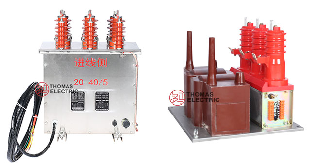
Product Shows


ZWJLSZ-12 prepaid metering box main view showing stainless steel cylindrical enclosure

Internal structure of ZWJLSZ-12 showing circuit breaker and instrument transformers


Side view of ZWJLSZ-12 with vacuum circuit breaker and transformer assembly
Working Principle
The ZWJLSZ-12 operates through integration of three primary subsystems: the vacuum circuit breaker provides circuit interruption and protection, the combined instrument transformers (CT/VT) measure electrical parameters for metering and protection, and the prepaid control unit manages energy consumption based on prepayment status. The vacuum circuit breaker utilizes spring mechanism operation to achieve fast switching with opening and closing times under 60ms. Current transformers with epoxy resin vacuum integral casting deliver accurate current measurement for multiple ratios from 10/5₁:5 to 300/150₁:5, while voltage transformers provide 10₂ 0.1:0.22kV transformation for metering accuracy class 0.2 and protection class 3.
System Application Position
- Prepaid Power Distribution: Residential, commercial, and industrial facilities requiring prepaid metering
- Medium-Voltage Feeders: 6-10kV distribution networks with load management requirements
- Branch Circuit Protection: Dedicated transformer protection and metering applications
- Remote Monitoring: Smart grid integration with remote control and data acquisition capability
Structural Overview
Stainless steel cylindrical enclosure construction provides superior corrosion resistance for outdoor installation. The integrated design combines vacuum circuit breaker, epoxy resin cast instrument transformers, and control/metering electronics in a single weatherproof housing. Spring mechanism operation enables both manual and electric control modes with energy storage function for operation during power outages.
Service Conditions
The ZWJLSZ-12 prepaid metering box is designed for outdoor operation under normal service conditions in medium-voltage power distribution systems.
Installation Environments
- Installation environment: Outdoor installation
- Altitude: Not exceeding 2000 m above sea level
- Ambient temperature: −35°C to +40°C
- Relative humidity: Daily average ≤ 95%, monthly average ≤ 90%
- Saturated vapor pressure: Daily average ≤ 2.2 MPa, monthly average ≤ 1.8 MPa
- Seismic rating: Not exceeding magnitude 8
- Pollution level: Anti-pollution level III
- Environmental conditions: Free from fire, explosion hazards, chemical corrosion, and severe vibration
Construction
Construction Design
- Enclosure: Stainless steel cylindrical housing with outdoor weatherproof construction
- Circuit breaker: ZW8-12 outdoor AC vacuum circuit breaker with spring mechanism
- Transformers: Epoxy resin vacuum integral casting (CT and VT)
- Control system: LDOEJ-R three-phase combination high-voltage cost control device
- Operating mechanism: Manual/electric spring mechanism with energy storage
- Isolation switch: Multi-insulation material with hydrophobicity and anti-condensation properties
Circuit Breaker Components
The ZW8-12 vacuum circuit breaker features operating mechanism, conductive circuit, insulation system, sealing components, and shell assembly in three-phase common box configuration. The conductive circuit comprises conductive brackets, vacuum arc extinguisher, thermal insulating plates, conductive through composite insulator, and arc suppression grids. Spring mechanism operation provides synchronized opening/closing with mechanical interlock for safety.
Transformer Configuration
Current transformers and voltage transformers utilize epoxy resin vacuum integral casting for superior insulation performance and moisture resistance in outdoor environments. Multiple current transformer ratios available from 10/5₁:5 to 300/150₁:5 with accuracy class 0.2s for metering applications. Voltage transformer provides 10₂ 0.1:0.22kV transformation with dual accuracy classes: 0.2 for metering (20VA) and 3 for protection (50VA).
Anti-Misoperation Features
- Isolation switch cannot open when line voltage is present
- Isolation switch operation permitted only when circuit breaker is open
- Surge protection function with time delay to prevent misoperation during transients
- Visible disconnection points for safe maintenance during power outages
Windings & Terminal Marking
Vacuum Circuit Breaker Primary Terminals:
- Incoming terminals: P1A, P1B, P1C
- Outgoing terminals: P2A, P2B, P2C
Current Transformer Secondary Terminals:
- CT Phase A: 1S1/1S2
- CT Phase B: 2S1/2S2
- CT Phase C: 3S1/3S2
Voltage Transformer Secondary Terminals:
- VT metering winding: 1a/1n
- VT protection winding: 2a/2n
Data Reference
Technical parameters are specified per nameplate and factory test report. Values shown represent standard configurations; custom specifications available upon request.
Vacuum Circuit Breaker Ratings
| Parameter | Value |
|---|---|
| Rated voltage | 12 kV |
| Rated load | 5000 kVA |
| Rated short-circuit closing current (peak) | 50 kA |
| Rated short-time withstand current | 20 kA |
| Rated short-time withstand current duration | 4 s |
| Rated peak withstand current | 50 kA |
| Control circuit voltage | AC 220V ± 10% |
| Average opening speed | 1.1 ± 0.2 m/s |
| Average closing speed | 0.8 ± 0.2 m/s |
| Closing time | ≤60 ms |
| Opening time | ≤60 ms |
Current Transformer Specifications
| Rated Transformation Ratio |
Rated Secondary Current |
Accuracy Class |
Rated Burden |
|---|---|---|---|
| 300/150₁:5 | 5 A | 0.2s class | 10 VA |
| 200/100₁:5 | |||
| 150/75₁:5 | |||
| 120/60₁:5 | |||
| 100/50₁:5 | |||
| 80/40₁:5 | |||
| 60/30₁:5 | |||
| 50/25₁:5 | |||
| 40/20₁:5 | |||
| 30/15₁:5 | |||
| 20/10₁:5 | |||
| 10/5₁:5 |
Voltage Transformer Specifications
| Rated Transformation Ratio | Rated Capacity and Accuracy Class |
|---|---|
| 10₂ 0.1:0.22 kV | Metering: 10:0.1 kV, 20 VA, 0.2 class Protection: 10₂0.22 kV, 50 VA, 3 class |
Standards & Normative References
The ZWJLSZ-12 prepaid metering box is manufactured in accordance with the following standards:
- IEC 61869-1: Instrument transformers – General requirements
- IEC 61869-2: Additional requirements for current transformers
- IEC 62271-100: High-voltage switchgear and controlgear – Alternating current circuit-breakers
- GB/T 20840.1: Instrument transformers – Electronic instrument transformers – Part 1: General requirements
- GB/T 20840.2: Instrument transformers – Part 2: Additional requirements for current transformers
- GB 3906: 3.6-40.5kV AC high voltage load switches and combined electrical appliances
Factory Test Compliance
Each ZWJLSZ-12 unit undergoes comprehensive factory testing prior to delivery:
- Vacuum circuit breaker tests: Mechanical operation, contact resistance, insulation resistance, dielectric withstand
- Instrument transformer tests: Ratio verification, accuracy class confirmation, burden test, insulation resistance, dielectric withstand
- Control system tests: Prepaid function verification, remote control operation, protection coordination
- Assembly tests: Overall insulation level, mechanical interlock function, terminal connection verification
- Visual and dimensional inspection: Marking verification, nameplate accuracy, workmanship conformity
Installation & Dimensions
- Outline dimensions and mounting details provided in dimensional drawings
- Device shall be securely mounted using designated fixing brackets on concrete foundation or mounting frame
- Primary conductor connections made via overhead line terminals or cable lugs per site requirements
- Adequate clearance maintained for insulation coordination, heat dissipation, and maintenance access
- Control and metering cable entries sealed with weatherproof glands
Outlines
ZWJLSZ-12 Assembly Configuration

Connection Diagrams
Primary Circuit Wiring

Secondary Circuit Wiring (CT/VT and Control)

Ordering Information
When placing an order, the required configuration shall be specified according to local grid requirements, applicable standards, and project technical specification. The following parameters shall be clearly stated for technical confirmation and production release:
- System voltage class: 6kV or 10kV (specify rated voltage)
- Current transformer ratio: Select from available ratios 10/5₁:5 to 300/150₁:5
- Voltage transformer configuration: Standard 10₂ 0.1:0.22kV or custom specification
- Rated secondary current: 5A (1A available upon request)
- Accuracy requirements: Metering 0.2s class, Protection 3 class (custom accuracy upon request)
- Operating mechanism: Manual, Electric, or Manual/Electric combined
- Control system: Prepaid control configuration and communication protocol
- Enclosure material: Stainless steel (standard) or custom coating specification
- Environmental specifications: Operating temperature range, altitude, pollution level requirements
- Documentation and certificates: Language preference, required test certificates, compliance documentation
Selection Steps:
1. Determine system voltage (6kV or 10kV) and feeder load capacity to confirm device rating
2. Select CT ratio based on maximum load current and required measurement range (typically 120-150% of normal operating current)
3. Verify VT configuration matches metering and protection requirements per utility standards
4. Confirm prepaid control system requirements including communication interface and remote control functions
5. Specify operating mechanism based on installation location and operational requirements (manual for basic applications, electric for remote control)
6. Review environmental conditions and confirm device ratings meet installation site requirements
If local utility or project requirements apply (e.g., special insulation levels, terminal arrangements, mounting configurations, or documentation language), specify them at the ordering stage. Custom configurations shall be confirmed by technical agreement and final data sheet prior to production.